• The move to the new server is done. There are some software and database maintenance updates in process. This has us passing the hat around to help out. We appreciate any donations. Seriously, even a dollar helps. The payment page may be found here - https://www.audiokarma.org/support.html

Pioneer SX-1280 with Hum in the Audio

Brivan

Well-Known Member
Hello, everyone

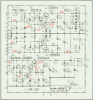
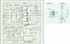
I've been trying to diagnose a low-level audio hum in a Pioneer SX-1280 but, so far, have come up with nothing. I've read other threads in the Pioneer forum that have dealt with the same hum issue, but my situation appears to be a bit different from the others.

The receiver appears to be all original, with no apparent mods to wiring or components. I've checked voltage readings from the power supply and protection boards and all are normal. I've replaced all electrolytic capacitors on the power supply board as a preemptive strike, but the hum noise remains.

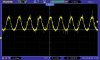
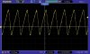
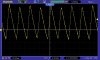
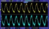
I get the humming regardless of what's done with any of the controls on the front (except for the speaker switches, of course). The hum quiets down considerably with the preamp out / main amp in jumpers removed, but it's still present and somewhat more pronounced in the left channel. The hum is in the speaker outputs as well as the headphone jack output. O-scope audio screenshots taken were connected to the headphone jack.

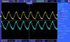
If anyone has any insight as to what I should look for next, it would be appreciated. Are the 4mV ripple voltages coming from both the +32v and -32v power supplies normal, or should they be flatter? The waveforms seen are pretty much a constant 120Hz - due to the irregularity of the waveforms, my scope got a little confused on some of them, but the sec/div adjustment knob was left the same for all readings. I'm assuming this is going to be a grounding issue, but I haven't seen any obvious grounds disconnected.

Below are screenshots from my scope.

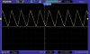
+32v from power supply board:
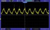
+32v Scope Reading.jpg

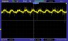
-32v from power supply board:
-32v Scope Reading.jpg

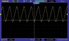
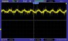
+13v from power supply board:
+13v Scope Reading.jpg

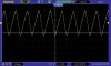
Audio output with jumpers installed:
Audio Output Scope Reading - Jumpers Installed.jpg

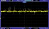
Audio output with jumpers removed:
Audio Output Scope Reading - Jumpers Removed.jpg

Thanks!
 
Register to hide this ad
I suspect more artifacts from your probing and your ground choices for the probe,

The +/- 68v supply and it's ripple supply the +/- 32v zeners so I can't see more ripple showing up on the 32v rails thanthe 68v rails..

All 4 supplies go straight in to the power amps.

Check the 4 BIG caps, DC and AC (dc blocked by cap) voltages at each.
Also check the snubbers.

Remember, each channel has it's own pair of big caps for unregulated wattage that is sent to the speakers.
.
 
The regulators are powered by (and sensitive to ripple here) by the R1 and C7 (R2 & C8 on the negative supply) filters.
later models used current regulator "diodes" in place of R1/R3 (R2/R4 on the negative supply) for ripple rejection.


upload_2022-6-30_15-21-18.png
 
on top of that, there's the common misconceptions about ground.

Stop thinking of it as an absolute, and start considering it as the return current flowing through ground resistance.
Milliamps and milliohms is still millivolts.

Thus you want a power return separate from a signal reference ground.

This is why you see 0.01uf capacitors between a RCA jack shell and the chassis itself.

There were a lot of short cuts done in the models (where they could get away with it), the Spec-1 ground setup is a revelation and education.
Unfortunately it only shows up IRL, not in the service manual.
 
on top of that, there's the common misconceptions about ground.

Stop thinking of it as an absolute, and start considering it as the return current flowing through ground resistance.
Milliamps and milliohms is still millivolts.

Thus you want a power return separate from a signal reference ground.

This is why you see 0.01uf capacitors between a RCA jack shell and the chassis itself.

There were a lot of short cuts done in the models (where they could get away with it), the Spec-1 ground setup is a revelation and education.
Unfortunately it only shows up IRL, not in the service manual.
Thanks for everything you've posted today, Mark! I'll get back in the saddle tomorrow morning and will post whatever measurements / findings I come up with.
 
The regulators are powered by (and sensitive to ripple here) by the R1 and C7 (R2 & C8 on the negative supply) filters.
later models used current regulator "diodes" in place of R1/R3 (R2/R4 on the negative supply) for ripple rejection.


View attachment 2604651
Okay, here's what I have, so far: I pulled and checked R1 & R2 from the power supply board and both tested good at 2.7k. I reinstalled both and powered the receiver up. I took the following measurements at the main caps, C1 - C4:
C1 64v
C2 -63.8v
C3 64.2v
C4 -64.1v
Note these voltages are a tad low as I'm connected to mains power via the DBT shown in my signature pic. I have all three switches on, so it's operating through three 60-watt bulbs in parallel.
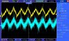
Waveforms taken from each main cap are below.

C1:
C1.jpg

C2:
C2.jpg

C3:
C3.jpg

C4:
C4.jpg

I assume the snubber caps you're referring to are at both the main power switch and the fuse PCB? Is there a preferred way to test these?
 
you didn't take the AC voltages at c1, c2, c3, c4.

You need a dc blocking capacitor in series with your dmm probe. 0.1uf 100+ v metal film or other non-polarized cap.
Then measure the AC voltage at each cap's terminals.

I notice something different between the c1, c3 traces and the c2, c4 traces.

upload_2022-7-1_23-59-25.png
 
you didn't take the AC voltages at c1, c2, c3, c4.

You need a dc blocking capacitor in series with your dmm probe. 0.1uf 100+ v metal film or other non-polarized cap.
Then measure the AC voltage at each cap's terminals.

I notice something different between the c1, c3 traces and the c2, c4 traces.

View attachment 2605918
With a 0.1uF capacitor in series with my positive meter lead, I get the following:
C1 11.3mV AC (orange wires)
C2 11.4mV AC (white wires)
C3 11.4mV AC (red wires)
C4 12mV AC (white wires)
 
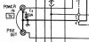
A curious observation while I was trying to drill down the problem: I found that when I grounded either one of the left or right pre out / main in RCA jack shells, the 120Hz ripple in the audio output in both channels was reduced by about half. Grounding both channels had just slightly better results than only grounding one channel. I see where pin 4 of the amp boards is grounded at the main in RCA jack and, on the left channel, a .o4uF capacitor is also in place. I don't completely understand this - the parallel configuration of the capacitor to ground as well as a straight connection to ground. Seems the purpose of the capacitor would be defeated.
Capture.JPG
 
Last edited:
no. the ground at that point probably has DC + ripple on it. only a few millivolts, but that's enough.

the capacitor makes sure that the incoming ground routes all it's ac interference to the chassis.
without disturbing the grounding setup.
were you to short the capacitor when properly working, there would be more noise.

back to the first request, the ac volts on the dc caps... nothing stands out.

while...

the oscope traces shows modulated peak heights on trace 1 and 3. this is probably an effect of the hum you are chasing.
 
no. the ground at that point probably has DC + ripple on it. only a few millivolts, but that's enough.

the capacitor makes sure that the incoming ground routes all it's ac interference to the chassis.
without disturbing the grounding setup.
were you to short the capacitor when properly working, there would be more noise.

back to the first request, the ac volts on the dc caps... nothing stands out.

while...

the oscope traces shows modulated peak heights on trace 1 and 3. this is probably an effect of the hum you are chasing.
Interesting to note that traces 1 & 3 are from C1 & C3 - which are both on the +76v part of the power supplies. Unfortunately, I don't know what that might mean - if anything. I'm running out of ideas on this thing. I hate to lose a battle and call something good-enough, but it might be the case, here. It's a nice receiver and would be very usable with just speakers connected to it. Headphones would likely reveal the audio hum during quiet passages. Thanks, Mark, for your help with this. I'll probably push this project aside and get my brain away from it for awhile.
 
I implied a suggestion to increase the hum rejection of the regulated power supplies, by removing C7 and replacing R1 & R3 with a CRD.
post #3. For the opposite polarity, by removing C8 and replacing R2 & R4 with a CRD.
Like it is done in some models.

Then you at least know the +/- 68v and +/- 32v supplies are blameless.

Is it quiet with the pre-out / amp-in jacks disconnected?

If so, It's coming in with the preamp signal.

Then you short at the jack the input (say - aux) and start looking for where it appears.
 
I implied a suggestion to increase the hum rejection of the regulated power supplies, by removing C7 and replacing R1 & R3 with a CRD.
post #3. For the opposite polarity, by removing C8 and replacing R2 & R4 with a CRD.
Like it is done in some models.

Then you at least know the +/- 68v and +/- 32v supplies are blameless.

Is it quiet with the pre-out / amp-in jacks disconnected?

If so, It's coming in with the preamp signal.

Then you short at the jack the input (say - aux) and start looking for where it appears.
I'd be willing to change the configuration of the power supplies as you suggested. Do you know what component(s) I should use for a CRD?

The hum noise is lessened with the pre out / main in jumpers removed (as shown in my initial post), but it's still audible. The hum is reduced from about 100mV P-P to about 10mV P-P with the jumpers removed.

Additionally, switching to Aux Input and adding shorting plugs to both jacks makes no difference in the audio waveform or the hum amount of hum heard through the speakers.
 
Last edited:
crd is mouser.com 954-E-202 at about a buck each.
954-E-272 has 79 at 2.7 mA and $0.97 as a reasonable substitute.

i believe in february on a sx-880 we had a similar conversation...

upload_2022-7-8_0-23-9.png
 
Last edited:
crd is mouser.com 954-E-202 at about a buck each.
954-E-272 has 79 at 2.7 mA and $0.97 as a reasonable substitute.

i believe in february on a sx-880 we had a similar conversation...

View attachment 2610600

Okay, the power supply modification has been done according to your schematic. Hum is still audible in the speakers, but not as loud, as evidenced by the waveforms I'm seeing. In my first post, the waveforms were about 100mV P-P. Now they're around 30 - 40mV P-P, so I feel progress has been made. On a side note, it seems it takes a bit longer for the main caps to charge on power-up - I was getting ready to hit the power switch, but my DBT did finally dim down.

If you have any more suggestions, I'll gladly take them!

Audio Out After Power Supply Mod.jpg
 
look at the waveform at the base of Q1 & Q2.
Then at the emitters of Q1 & Q2.
then on pins 9 & 10 (i know, it's ground..)

in all cases your scope ground should be a bare metal chassis ground AWAY from the point where the transformer center taps are grounded.
 
look at the waveform at the base of Q1 & Q2.
Then at the emitters of Q1 & Q2.
then on pins 9 & 10 (i know, it's ground..)

in all cases your scope ground should be a bare metal chassis ground AWAY from the point where the transformer center taps are grounded.
I had a small disaster, today, and feel rather stupid about it. On my first measurement of the base of Q2, I somehow managed to short the grounding ring of the scope probe to something - not sure what. This idiotic move ended up in the ruination of Q2 & Q4. Q2 was replaced with MJE15033 & Q4 was replaced with KSA1013. At the same time, I replaced Q1 with MJE15032. The power supply voltages all tested good, but I'm certain I killed most, if not all, ICs on the tuner board. I now get a stereo beacon when selecting any function except FM and the signal strength meter pegs when AM is selected. Yup, I feel pretty stupid and I have since covered that scope probe grounding ring with shrink tube.

Aside from that, here are the scope results from the test points you requested: Probe ground wire was clipped to the frame right by the left rear tuning string pulley.

Q2 base - about 700mV P-P:
Q2 Base.jpg

Q1 base - about 600mV P-P:
Q1 base.jpg

Q2 emitter - about 700mV P-P:
Q2 Emitter.jpg

Q1 emitter - about 600mV P-P:
Q1 Emitter.jpg

Pin 9 - about 1mV P-P:
Pin 9.jpg

Pin 10 - about 1mV P-P:
Pin 10.jpg
 
look at the waveform at the base of Q1 & Q2.
Then at the emitters of Q1 & Q2.
then on pins 9 & 10 (i know, it's ground..)

in all cases your scope ground should be a bare metal chassis ground AWAY from the point where the transformer center taps are grounded.
Thanks for your help, Mark. If there are no further ideas (from you or anyone else who has followed this thread), I'll hopefully get the tuner back on its feet, reassemble this thing and get it off my bench. As stated in a previous post, it'll likely work fine as a speakers-only receiver.
 
Just wanted to offer my thoughts on the hum. I assume you're in the US (120Hz Hum). So is the receiver connected in to the mains with a two prong plug? Does the receiver have one of those 2.2M ohm resistors tying one of the mains feeds to the chassis? Maybe that's starting to open up? Also, have you checked for earth leakage if you do ground the chassis to true earth ground? You've probably done all this but just a thought.
 
Back
Top Bottom