• The move to the new server is done. There are some software and database maintenance updates in process. This has us passing the hat around to help out. We appreciate any donations. Seriously, even a dollar helps. The payment page may be found here - https://www.audiokarma.org/support.html

Pioneer SX-1280 with Hum in the Audio

Just wanted to offer my thoughts on the hum. I assume you're in the US (120Hz Hum). So is the receiver connected in to the mains with a two prong plug? Does the receiver have one of those 2.2M ohm resistors tying one of the mains feeds to the chassis? Maybe that's starting to open up? Also, have you checked for earth leakage if you do ground the chassis to true earth ground? You've probably done all this but just a thought.
Hi, and thanks for the suggestions. Yes, I'm in the US and have verified the hum signal at 120Hz. I measured the 2.2Mohm resistor and it tested fine at about 2.29Mohms. I also tried tying the frame of the receiver to ground via an electrical outlet ground, with no noticeable difference in the audio waveforms on the o-scope. So far, the greatest reduction in hum was from modifying the power supply per Mark's instructions above.
 
Ok, good to know. Just another thought, but are any of the regulated power supplies in the unit oscillating at high frequency? This can happen if a slow regulator transistor that was originally say 4MHz is changed to something like the MJE15032 which is rated for around 30MHz (IIRC). The regulator circuit doesn't always have sufficient damping for oscillation or it was never added specifically because they used a slower transistor. Probe all the regulated lines and just check that there isn't some other waveform above 120Hz somewhere. In my experience it was a bit obvious and was usually in the MHz range. Again, maybe you've already looked, though on the schematic posted, it looks like there could be cause for oscillation if a higher speed transistor has been used somewhere...
 
Ok, good to know. Just another thought, but are any of the regulated power supplies in the unit oscillating at high frequency? This can happen if a slow regulator transistor that was originally say 4MHz is changed to something like the MJE15032 which is rated for around 30MHz (IIRC). The regulator circuit doesn't always have sufficient damping for oscillation or it was never added specifically because they used a slower transistor. Probe all the regulated lines and just check that there isn't some other waveform above 120Hz somewhere. In my experience it was a bit obvious and was usually in the MHz range. Again, maybe you've already looked, though on the schematic posted, it looks like there could be cause for oscillation if a higher speed transistor has been used somewhere...
The receiver was exhibiting the hum symptoms before the original regulator transistors in the power supply were replaced., but I can certainly have a look with the scope to see if any higher frequencies are detected.
 
The receiver was exhibiting the hum symptoms before the original regulator transistors in the power supply were replaced., but I can certainly have a look with the scope to see if any higher frequencies are detected.
Sorry for the late response - I was on vacation last week and didn't think to post anything about it before I left! Today, I measured the regulated supplies looking for anything significant in the Mhz range, but didn't see anything other than some random noise through the scope probe.

@markthefixer - is there anything else you can think of that I should look for before calling this one good enough?
 
Not really, the next step would be to pull and test or replace the snubber caps (0.01uf 250v) across the rectifiers.
Last step would be the rectifiers, looking for a noisy one. You don't want a FAST rectifier, they're noisier.
 
Not really, the next step would be to pull and test or replace the snubber caps (0.01uf 250v) across the rectifiers.
Last step would be the rectifiers, looking for a noisy one. You don't want a FAST rectifier, they're noisier.
Okay, thanks, Mark. I'll have a look at those things tomorrow.
 
Not really, the next step would be to pull and test or replace the snubber caps (0.01uf 250v) across the rectifiers.
Last step would be the rectifiers, looking for a noisy one. You don't want a FAST rectifier, they're noisier.
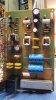
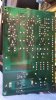
Okay, I removed, replaced and tested D1 - D4 and C1 - C4. The diodes tested good and the capacitors tested at about 8nf each. Diodes were replaced with 1N4004 and capacitors were replaced with .01uf 300v. I'm attaching an image of both side of the power supply board for reference. I've still got the 120Hz audio hum, but it doesn't become noticeable until about 45 seconds to a minute after power-up. This could have been happening all along and I just didn't notice it because I possibly didn't start taking measurements until after this time had elapsed, but I can't be sure. I'll provide details in the following message.

Component side of power supply board:
Power Supply Board - Components Side.jpg

Foil side of power supply board:
Power Supply Board - Foil Side.jpg
 
Not really, the next step would be to pull and test or replace the snubber caps (0.01uf 250v) across the rectifiers.
Last step would be the rectifiers, looking for a noisy one. You don't want a FAST rectifier, they're noisier.
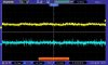
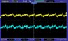
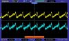
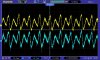
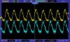
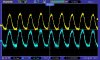
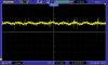
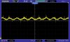
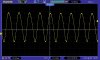
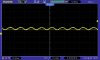
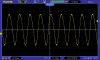
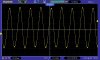
And now for the audio hum not becoming noticeable until about a minute after power-up. I took measurements of the audio, +32v, -32v, +68v and -68v supplies at different times after power up to give you a better idea of what's happening. Here are the audio waveforms.

Audio at 1 second after power-up:
Audio Output 1 Second After Power-Up.jpg

Audio at 5 seconds after power-up:
Audio Output 5 Seconds After Power-Up.jpg

Audio at 25 seconds after power-up:
Audio Output 25 Seconds After Power-Up.jpg

Audio at 35 seconds after power-up:
Audio Output 35 Seconds After Power-Up.jpg

Audio at 45 seconds after power-up:
Audio Output 45 Seconds After Power-Up.jpg

Audio at 50 seconds after power-up:
Audio Output 50 Seconds After Power-Up.jpg

Audio at 55 seconds after power-up:
Audio Output 55 Seconds After Power-Up.jpg

Audio at 60 seconds after power-up:
Audio Output 60 Seconds After Power-Up.jpg
 
Not really, the next step would be to pull and test or replace the snubber caps (0.01uf 250v) across the rectifiers.
Last step would be the rectifiers, looking for a noisy one. You don't want a FAST rectifier, they're noisier.
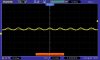
And here are the power supply waveforms.

+32v:
+32v Supply.jpg

-32v:
-32v Supply.jpg

+68v supply 1 second after power-up:
+68v Supply 1 Second After Power-Up.jpg

+68v supply 5 seconds after power-up:
+68v Supply 5 Seconds After Power-Up.jpg

+68v supply 30 seconds after power-up:
+68v Supply 30 Seconds After Power-Up.jpg

+68v supply 60 seconds after power-up:
+68v Supply 60 Seconds After Power-Up.jpg

-68v supply 1 second after power-up:
-68v Supply 1 Second After Power-Up.jpg

-68v supply 5 seconds after power-up:
-68v Supply 5 Seconds After Power-Up.jpg

-68v supply 30 seconds after power-up:
-68v Supply 30 Seconds After Power-Up.jpg

-68v supply 60 seconds after power-up:
-68v Supply 60 Seconds After Power-Up.jpg
 
@markthefixer I don't mean to be a pest, Mark, but I wanted to make sure you were notified of my last few posts showing the audio noise and power supply ripple ramping up to about the one-minute mark after power-up. I thought it was an interesting symptom that you might want to weigh in on. Thanks.
 
I guess you've double checked that all the capacitors are in the correct orientation? When this happens after 30-45 seconds of being powered up, what is the regulated voltage measured at vs the unregulated voltage? It looks like your power supply rails are going down and the regulators are dropping out of regulation. Are you running this on a DBT at the moment?
 
I guess you've double checked that all the capacitors are in the correct orientation? When this happens after 30-45 seconds of being powered up, what is the regulated voltage measured at vs the unregulated voltage? It looks like your power supply rails are going down and the regulators are dropping out of regulation. Are you running this on a DBT at the moment?
I went over capacitor orientation a couple times before power-up after replacing them, but it wouldn't hurt to check again. The receiver has been on a DBT the entire time I've been working on it. The DBT is shown in my member photo and I currently have it running through all three 60-watt bulbs in parallel. This is a goofy problem and I'm a little leery of some of the steps I've taken to alleviate it, so I've left the receiver on DBT. I won't be back into the shop until Monday, but I'll verify capacitor orientation and report back with voltage measurements from the regulated and unregulated supplies at that time. Thanks for getting back to me!
 
Check those voltages.... its starting to sound like the DBT is dragging the voltages down and knocking everything out of regulation... the question would be then, is it because the idle current is too high. Have you set the idle current? If so, set it back to 0mV.
 
Check those voltages.... its starting to sound like the DBT is dragging the voltages down and knocking everything out of regulation... the question would be then, is it because the idle current is too high. Have you set the idle current? If so, set it back to 0mV.
I did recheck the DC offset and idle current after replacing D1 - D4 and C1 - C4. Oddly, the offset on both channels was at around 150mV (I don't recall if it was + or -), so I got both back to around 0mV. The idle current on both sides was right about at spec - which, I believe, was around 20mV. Tomorrow I'll try the receiver without the DBT and will check the supply voltages you suggested in a previous post. Thanks!
 
If you're moving from a DBT to direct wall power you MUST SET IDLE CURRENT TO MINIMUM. The DBT effects all voltages in the amplifier and it is not uncommon to for the idle current to jump very drastically when the figurative leash is removed. Then Fido, the friendly output transistor very quickly runs away, never to be seen again... if you catch my drift... :eek::idea:

Before doing that however, are all the 60W bulbs glowing/bright/dim? Does their glow increase in relation to the hum developing over the minute after power up etc?

I'm not familiar with what the idle current for the SX-1280 should be so its best double checked in the service manual. But definitely start it from 0mV after its connected to the mains without DBT.
 
If you're moving from a DBT to direct wall power you MUST SET IDLE CURRENT TO MINIMUM. The DBT effects all voltages in the amplifier and it is not uncommon to for the idle current to jump very drastically when the figurative leash is removed. Then Fido, the friendly output transistor very quickly runs away, never to be seen again... if you catch my drift... :eek::idea:

Before doing that however, are all the 60W bulbs glowing/bright/dim? Does their glow increase in relation to the hum developing over the minute after power up etc?

I'm not familiar with what the idle current for the SX-1280 should be so its best double checked in the service manual. But definitely start it from 0mV after its connected to the mains without DBT.
Well, this is interesting (and maybe a little embarrassing) - I plugged the receiver into mains power and powered it up while monitoring the idle current on one of the channels and it came up with absolutely no humming noise in either the left or right channel. I connected the scope to the audio outputs to verify and all I saw was a bit of noise. The idle current was about 5mV too high at 20mV, so I adjusted both channels down to 15mV. I powered down, waited a few minutes, then reconnected to the DBT and powered up, again. Once again, I had the waveform patterns as previously posted and a 120Hz hum in both channels. Your speculation about the regulated supplies coming out of regulation was evidently spot-on!

I'm not 100% sure at what point the hum problem was actually fixed (the original problem was a hum when connected to mains power). But my best guess is C1 - C4, which only measured around 0.8nF each, instead of 0.01uF were the likely cause (though D1 - D4 were replaced at the same time, but tested good out of circuit). I've had SX-1280s on the bench, before, and never had problems with audio hum while connected through the 3-lamp DBT, so I'm a bit at a loss as to why this one is different. The power supply was modified early-on (as suggested by Mark the Fixer), so maybe that mod made the power supply more apt to produce audio hum when connected through a DBT? I dunno.

When the receiver is connected through the 3-lamp DBT, there is no discernible glow in the lamps (after a few-second glow while charging the main caps). I can still provide you with voltage measurements, if you're curious.
 
Hooray! :jump:

Its a tentative fix. Just go through all the voltage regulators pre and post voltages and make sure everything looks ok.

Maybe on thing to think of as to why this one is different is maybe the primary voltage selector (if it has one) and perhaps the tungsten panel lamps? These do draw quite a bit of power when compared to idle power consumption so if these were off/out/dead/converted to LEDs on other ones, that might point to a discrepancy.

My DBT is made up of three bulb holders - one permanently wired and two switchable. That way, I can mix and match wattages and also check how an amp behalves with a little bit less or more "leash". If I'd had you're problem, I would have switched an extra bulb into circuit briefly to see if that stopped it.

In the end there's been a lot of changes. Might be worth cataloguing/listing them and having a little look. I would suggest i probably isn't C1 - C4. I often find them at around 8nF and I do change them anyway. It could've been a bad diode...?

 
Hooray! :jump:

Its a tentative fix. Just go through all the voltage regulators pre and post voltages and make sure everything looks ok.

Maybe on thing to think of as to why this one is different is maybe the primary voltage selector (if it has one) and perhaps the tungsten panel lamps? These do draw quite a bit of power when compared to idle power consumption so if these were off/out/dead/converted to LEDs on other ones, that might point to a discrepancy.

My DBT is made up of three bulb holders - one permanently wired and two switchable. That way, I can mix and match wattages and also check how an amp behalves with a little bit less or more "leash". If I'd had you're problem, I would have switched an extra bulb into circuit briefly to see if that stopped it.

In the end there's been a lot of changes. Might be worth cataloguing/listing them and having a little look. I would suggest i probably isn't C1 - C4. I often find them at around 8nF and I do change them anyway. It could've been a bad diode...?
There's no voltage selector on the receiver, but the incandescent-to-LED conversion of the indicator lamps could maybe invoke some goofy characteristics, although I've done the same conversion on the other SX-1280 receivers I've had on my bench and don't recall a prevalent audio hum but, then again, I wasn't really listening for it. From a few feet away of my bench speakers, the audio hum can't be heard.

D1 - D4 tested good in-circuit and out-of-circuit but who knows - maybe one was breaking down with power applied?

My DBT is shown in my member photo and all three lamps are switched. I use it the same as you. I'll generally start with two lamps in-circuit for medium-wattage receivers, but will use all three for higher-wattage units like the SX-1280. I typically leave the receiver connected to the DBT until I'm ready to put the cover back on. At that time I'll do another adjustment of the offset and idle current while plugged in to mains power.

I made a dumb mistake a couple weeks ago while trying to diagnose the audio hum - I had the power supply board pulled out and forgot to put my insulator back between it and the protection board next to it. This act of carelessness resulted in the likely destruction of several tuner board ICs when the 13v regulator heat sink made contact with one of the rectifier assemblies on the protection board. The stereo beacon is always illuminated and the signal meter slams to the max when AM is selected. Heavy sigh. I'd prefer to just replace the tuner board rather than slugging my way through replacing whatever components might have been destroyed. I've got two spare tuner boards for an SX-980 & SX-1080 (AWE-094) and was trying to determine if they were swappable with the board in the SX-1280 (AWE-092). The only difference I can see is Q4, which is wired about the same on both boards, but is a different component from one board to the other. The AWE-094 uses an 8-pin DIP; the AWE-092 uses an 8-pin SIP. Everything else looks identical. I posted this issue in the Pioneer Audio forum but no takers, so far.
 
i saw tuner question - need time to research. jammed up rt now.

awe-094 980 has ha1201 dip and one less ceramic filter
awe-092 1080 has ta7302 sip
awe-092 1280 has ta7302 sip

all used as IF amp.

1080 1280 SAME board....grrr
 
Last edited:
i saw tuner question - need time to research. jammed up rt now.

awe-094 980 has ha1201 dip and one less ceramic filter
awe-092 1080 has ta7302 sip
awe-092 1280 has ta7302 sip

all used as IF amp.

1080 1280 SAME board....grrr
Yes, I discovered my misquote yesterday afternoon - the SX-1080 and SX-1280 use the same tuner board. A little odd since the 980 and 1080 are alike in so many other ways. So far, I haven't seen any differences in how the tuner board interfaces with the rest of the receiver so my plan, for now, is to do the swap. I've got the tuner board removed from the SX-1280 with plenty of photos and notes taken. The worst of it will be getting to the antenna connections on pins 1 & 2 with the solder and soldering iron while trying to see what I'm doing. I might try connecting those from the top side with the new tuner board unmounted. Thanks for your time!
 
Back
Top Bottom