• Please note that Audiokarma will be offline briefly for updates early on Monday morning, September 28th.

Pioneer sx-1980 FM dial calibration. I'm thinking about doing something that is considered taboo by the best Pioneer Tech I know. Edit: I gave up

zebulon1

Retired finally and having a blast on the bench
Subscriber
I have a SX-1980 that has a terrible dial tracking error.
It's over 1mhz shorter over the range of the dial.
It's spot on at 88mhz and tuning to 108mhz its pointer is located 106.8mhz.
When it tune's to the stations, it's spot on with good signal and very low distortion. It picks up fairly strong stations with no antenna and in stereo.
Basicly the tuning is perfect but the tracking is way off.
Markthefixer (MTF) has several warnings about the adjustment of this particular ALPS front end.
"When it comes to servicing the 1980 the legendary AudioKarma restoration expert (Mark) holds an absolute "Hard NO" policy against DIY adjustments on the FM front end".
"It's like handing out hand a grenade".


The VC has been cleaned and the shaft cleaned of corrosion and debris. This did improve the condition but not fix it.
The SM has a procedure which is the one Mark references as "Not a DIY procedure".

I would of probably tried the adjustment if I was sure of the location of the particular rotor/stator gang. The manual and the shield cover don't jive with each other (Very well). I think I have a good idea but am still hesitant of the process.
I have all the equipment need to do this and have done many successful alignments on other Pioneer models in the past.
The tracking is all that needs adjustment.
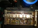
DSC08098.JPG

Screenshot 2026-09-19 093648.png
 

Attachments

Register to hide this ad
Here's my take on it.
Tracking means that the tuned stages are in alignment across the dial. Dial calibration means that the local oscillator is in alignment with the dial readings.
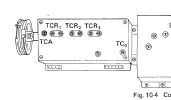
Usually you tune the coils for the low end and tune the VC and LO trimmer caps for the high end. In the case of the Alps RF FE, there are no coil cores to adjust, so one has to spread or compress the coils windings. The VC has trimmers built-in to the assembly, the LO has a separate trimmer. Since your dial is correct at 88MHz and off at 108MHz, try adjusting the LO trimming cap, the one that's shown in the right side compartment.
 
I was also going to say the thread title should say Pioneer sx-1980 FM dial calibration:-)
I agree, you can ask PunkerX, he is the most experienced guy we know on AK.
Bob on fmtuner forum has lots of experience too.
 
DO NOT touch the front end UNTIL your dial pointer is aligned properly, as in left and right the same overlap beyond the band edge. Only then start with the local oscillator. You will then find you will need to tweak all four RF LC circuits. The increasing offset is caused by the tuning cap not having enough control over the LO. This is because the inductor is too small and needs to be higher in value. The LO trimmer is set too high and needs to be set lower. You may then also find that the dial pointer is off but if it is still glued to its original position its usually better to leave it alone. Same with the tuning wheel on the tuning capacitor shaft.

If you have the right equipment (which?) you can certainly DIY this task. I use three: signal generator, multimeter (for absolute signal level) and a handy null indicator (zero center meter) for peaking. One more tip: first determine sensitivity (baseline) on 90 and 106 MHz before any adjustment. 26 dB quieting is a good benchmark.
 
I was also going to say the thread title should say Pioneer sx-1980 FM dial calibration:-)
I was trying to be dramatic. Sorry if I attracted the wrong crowd.

DO NOT touch the front end UNTIL your dial pointer is aligned properly, as in left and right the same overlap beyond the band edge. Only then start with the local oscillator. You will then find you will need to tweak all four RF LC circuits. The increasing offset is caused by the tuning cap not having enough control over the LO. This is because the inductor is too small and needs to be higher in value. The LO trimmer is set too high and needs to be set lower. You may then also find that the dial pointer is off but if it is still glued to its original position its usually better to leave it alone. Same with the tuning wheel on the tuning capacitor shaft.

If you have the right equipment (which?) you can certainly DIY this task. I use three: signal generator, multimeter (for absolute signal level) and a handy null indicator (zero center meter) for peaking. One more tip: first determine sensitivity (baseline) on 90 and 106 MHz before any adjustment. 26 dB quieting is a good benchmark.
Thanks for the detailed explanation. The follow-up adjustments must be what MTF was referring to?
 
What do you mean "wrong crowd"? The only ones participating should be those who have worked on one before and/or are familiar with such circuits. I worked on one once, now ~10 years ago. PE9ZZ has lots of experience not sure if he has worked on this particular Alps RF FE but they are all basically the same.
Ask PunkerX, he has the most experience. But your thread title would not be attracting his attention the way it was initially posted.
Good to see you made that correction.
As you know PunkerX moderates the tuner forum, so posting there should bring this to his attention or you can message him and post his responses here for us to read what he advises.
 
Last edited:
What do you mean "wrong crowd"?
Only meaning the membership that is not interested in the RF aspects.
I was hoping to draw out the RF experts but failed miserably. :whip:
I'll let this thread sit for a day or so. Maybe after the Title edit, other members will post. If not, I'll request a move to the tuner forum.
So far, I something to check out with your's and PE9ZZ suggestions.

Alps/Alpine manufactured that FE. Other manufactures used that same model FE and had different explanations and procedures to align it. I've been researching to see if the procedures are laid out differently.
 
I've been researching to see if the procedures are laid out differently.
They're all more or less the same. First LO, then RF. Low point inductors, 90 MHz, high point capacitors, 106 MHz. Simple physics. Even made a spreadsheet calculation for the optimum value for the low and high points so tracking is best. Attached "ter leringhe ende vermaeck" as they said in 17th century Holland. For learning and entertainment. A later version had the optima at 90.7 and 104.5 MHz. That one was optimized for PLL tuners.
 

Attachments

"ter leringhe ende vermaeck"
Definitely fits this situation.
The attempt to get this sorted out, is mainly to gain experience but the receiver is someone else's. I'm beginning to chicken out on getting this spot on.
He's been living with the offset for a long time and I can feel his (pain)? But is it worth the risk?
There's some bath remodeling to work this morning. Maybe rethink this?
 
But is it worth the risk?
What risk? You have the equipment and the knowledge. As long as you don't crack the fragile ferrite cores you'll be OK. You will need a good RF alignment tool. 2mm HEX. Hard to find nowadays.

Edit: Oh, darn, they have no cores and expect you to adjust the vanes (!) of the tuning cap. That's bad. What a lousy engineering solution.

Edit2: I now see the inductors are air coils. The silver ones. They can easily be tuned by compressing/expanding them. Veeeeeeeeerrrrrry carefully.
 
Last edited:
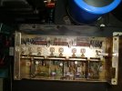
In the pic above I can't identify the LO inductor L(O):
pioneer_sx-1980_FE.png

That would be the place to start. The antenna coil L(A) is the vertical coil on the left. Tune it by inserting a piece of copper (lower) or ferrite (higher). The coils L(R2), R3 and R5 are the silver ones. I built many VHF front ends this way. Works like a charm.
 
I've never done one of these, so caveat emptor. I have, however, done various pieces of test equipment where bending the vanes for perfect tracking was necessary. The first thing to do is determine which gangs and coils are which. Put some temporary labels on the thing. More than once I've done an alignment and screwed it up by tweaking the wrong thing, usually near the end of the process. I would probably see if I could get the ends of the dial correct in the usual way, then fix the middle with the vanes. I'd also probably cheat and use a frequency counter (or scope with such) on the oscillator. Bending coil turns isn't bad unless they've been heavily doped up with something to... prevent bending. I've found some that were just too risky to bend. The big thing I'd be worrying about is not the process, but the why. It almost certainly left the factory correct, so what's changed? Am I making an adjustment that masks another problem that needs to be fixed?

Trivia- The old time radio service person's "tuning wand" was a rod with one end that could increase inductance and other reduce it. Not sure if they're useful today, but here's one- https://antiqueradios.com/forums/viewtopic.php?t=442223 It's large; smaller would be better now.

Public Service Announcement (just because it drives me nuts)- Megahertz is MHz. Millihertz is mHz.
 
If I use the magic wand near the coils I should see a change on the scope? Depending on the material, that would indicate whether the coils need to be opened or closed?
The tuning needs to spread open. 108.0MHz is reading 106.3MHz.
I actually did start tinkering with the coils yesterday. Only using my fingers and could see a deflection on the scope. I wasn’t using any force and the scope trace would return back to original tuned in trace. Mainly temporary detuning the frequency slightly.
 
Probably yes, but definitely with a counter. Just don't load the circuit measuring it. You'll want to make a very small tool, maybe with a 90 degree bend at the tip. Caveat emptor again, I haven't used this technique with anything modern. I can see that the coils are not glopped up with paint or epoxy, which is great. In theory this is doable, but I continue to ask, why? What changed?

edit- I just grabbed the service manual. The schematics are a muddy mess, but I note that the local oscillator involves a varicap diode. It's a fairly complex circuit. There could be all sorts of things going on and I'm now tempted to echo what Mark said!
 
Last edited:
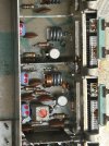
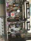
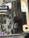
You must adjust L(o), the oscillator coil. I cannot locate it on your pic. Should be at the right side, very close to TC(o). Please make a closeup of that section, maybe that will help locating it and shed some light how to adjust it. Right now its value is too low (and TC(o)'s too high).

The varicap is just for AFC, it won't help with the offset. It is a needlessly complex circuit, in tune with this monster receiver.
 
I'm still exploring this and welcome all the input. I'd like to keep following through with this discussion, mainly for educational purposes. (Maybe for nefarious reasons).
The LO is the cavity to the far right housing the 2SK61, 2SC710 and the varicap diode. There is a trimmer cap that I messed with which is labeled as TC0.
TC0 is adjusted to get maximum signal and centered tuning after the dial calibration is achieved. Step 11, Page 34.
Should the exposed coils located in the other cavities should be left alone and the slotted screw trimmers on the VC adjustments for peaking?

Other things on my mind.
I have a HP3478 meter that works but is not calibrated. Probably trusty enough to get this FE dialed in.
A Sound Technology 3200 Analyzer which needs a sizable input to register. The REC lineout is not enough to get a THD reading. I can switch to Speaker out and get a reading.
A Sound Technology 1000a that works well and is trusted.
And: A HP5342A thats the coolest darn thing and seems to work perfectly against all the other equipment I have.
 

Attachments

  • IMG_9246.jpeg
    IMG_9246.jpeg
    171.5 KB · Views: 14
  • IMG_9245.jpeg
    IMG_9245.jpeg
    266.3 KB · Views: 14
  • IMG_9244.jpeg
    IMG_9244.jpeg
    264.5 KB · Views: 14
  • IMG_9243.jpeg
    IMG_9243.jpeg
    248.4 KB · Views: 12
  • IMG_9242.jpeg
    IMG_9242.jpeg
    194.3 KB · Views: 18
Back
Top Bottom