• The move to the new server is done. There are some software and database maintenance updates in process. This has us passing the hat around to help out. We appreciate any donations. Seriously, even a dollar helps. The payment page may be found here - https://www.audiokarma.org/support.html

Pioneer SX-1980 hum both channels

kmatch

Member
I’ve got a confusing one on the bench. It’s a Pioneer SX-1980 with hum in both channels.

The volume knob had no effect on hum volume.
Pulling the pre-amp to main amp pins and the hum is gone.
Driving the main amp directly from a portable MP3 player, hum is gone.

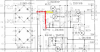
On the L/R outputs of the filter board (pins 9 and 11), if I short them to ground (pin 10), hum is still present.

If I short the “pre-amp to main amp” pins to the RCA shield, hum is gone. (Peculiar.)

I suspect this is a ground loop issue of current from the power amp flowing back to the RCA jack shields to the filter board pin 10 to ground, but haven’t been able to solve it. I have tried some different ground configurations to the star point but have only made it slightly worse in the process (maybe that’s a sign to confirm it’s a ground loop issue.). I’ve lifted the ground points from the chassis and they seem to be isolated from each other.

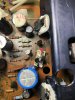
Only other peculiarities on the unit are that the power supply has seen damage and repairs. All rails have <4mV ripple except the +80V rail has about 50-70mV ripple at 0 volume. Also, most of the previous damage and repair on the power supply was on the +80V rail section. I’ve gone through the supply to check the caps and connections and so far checks out ok. (Will take another pass through for good measure.)

As for chassis ground points there is one main star point for the lower power supply. And there are two other chassis mounting points for left/right channels. It’s unclear to me which wiring is original and which is replaced so I’m unsure if the factory configuration of grounding is retained. On some of the back RCA inputs shields someone has placed ceramic caps soldered to the jack screw mounting points.

Any suggestions are welcome, since just thinking about this hummingbird is keeping me up at night.
 
Register to hide this ad
I’ve done some more checking of the power supply and I’m getting 35.6V on the Zener D212 and no base current through R218 (0.5mV DC and 0mV AC). Resistor on base of of negative rail has about 10mV DC and AC.

Seems like I’ve got no feedback in Q212.

I measure the voltage on R226 and Q214 is actually sinking current. Maybe my Zener is bad and causing a high voltage. Not sure if that’s a common failure mode though.

possibly related: the JFET resistor currents are different on the positive and negative rails:

Positive rail R214: Vdc=0mV, Vac=0mV
Negative rail R215: Vdc=33.7mV, Vac=33.5mV

So maybe something strange going on with the JFET too. Not sure which observation is causation and which is just correlation.

Related discussion on Zener failure modes
https://audiokarma.org/forums/index...e-failure-mode-troubleshooting-sx-1080.29015/
 
First off, get this moved over to the pioneer audio forum.

Then, what are all the regulated power supply voltages?
I'm not sure if we have listings documenting ac levels on the regulated DC.

I think your regulator power from Q206 is missing. Or goofy, through a failed circuit.

There is a constant current section that feeds the power regulators and they were used to quiet down the power.
Pioneer had two ways they did that for their regulator circuits:
one was a honking big RC filter (C was as big as the energy storage cap) that just a few clean mA were tapped off to run the regulator

upload_2021-6-18_21-7-13.png

The other was a constant current circuit.

upload_2021-6-18_21-7-57.png

The original constant current circuit (Q206, Q207) was working at it's limits for voltage etc... and failed often and easily.
Years back a reliable replacement was engineered. An "echowars" current source. Can be found splattered all over the pioneer audio forum.
Including MY wrinkle of building them on a 3 x 6 perfboard that took advantage of ebc pinouts.
Echowars had a small custom pc board that stood vertically, mine laid horizontally.


https://audiokarma.org/forums/index...-1980-restoration.841614/page-5#post-13091699
https://audiokarma.org/forums/index...-diodes-pioneer-sx-1980.823398/#post-11630378
https://www.audiokarma.org/forums/index.php?threads/pioneer-sx-1980-regulator-modification.618700/
https://audiokarma.org/forums/index...restoration-thread.440844/page-4#post-6842499
 
Last edited:
Mark the fixer, thanks for the response. Im new here so wasn’t sure how best to post it. Any other follow ups I’ll post over in the Pioneer section. I agree that something isn’t exactly right on my positive supply (since the +80V rail has 40mV ripple while all the others have about < 4mV ripple). But after reading and studying a bit more, I’m beginning to believe that my problem isn’t 120Hz buzz but is more of a hum (60Hz).

What’s particularly strange is that if I ground the Left/Right outputs at the filter board, the hum remains, but if I ground at the pre-amp to main input connector on the back, the hum is absent. I’m wondering if the cable from the filter board to the back panel is picking up hum via capacitive or magnetic coupling.

The main power wires to the +/- 80/34V board coming off of the transformer are arranged with some decent loops (and are not twisted). I’m considering twisting these a bit and then monitoring again. Still thinking on this a bit since it’s kind of strange to me. But I’m pretty new at this, so figuring out where to focus on is what I’m trying to better understand.
 
What are the current rail voltages? +80v, -80v, +34v, -34v, +13.5v, +8v ?

Reminds me of times where a ground foil on a board got the fuse treatment from some sort of fault ( in 'lesser' models).

This unit has a history unknown to you?


Mark the fixer, thanks for the response. Im new here so wasn’t sure how best to post it. Any other follow ups I’ll post over in the Pioneer section.
on the lower left of each post, there is a selector "report" next to the edit and delete keys. Hit report on your first post, and in the reason, ask to be moved to Pioneer Audio Forum. Usually it will get done, when the OP asks. Don't forget to thank the mod in advance :)
 
Last edited:
I did some more hum listening this time with headphones to get a better sense of the hum. Here are my findings.

Hum is present but volume is lowest when the pins connecting preamp to power amp are out.
Hum is next level up when filter board pins 9 and 11 are grounded to point 10.
Hum is next level up with normal operation.

Hum is not affected by the volume knob.

I’m fairly new at this so my ear isn’t tuned to 60 vs 120 Hz. If I had to guess, I’d say this is 120 Hz.


This unit has unknown history but there is significant damage and a rebuild on the power supply board. Most visible damage is on the +80V part of the board. There are some replacement transistors. There are some burned traces with jumpers. I added a couple more jumpers in sketchy areas of the PCB. I checked all the components with connections to ground (pin 10) and they are all connected. I’ve checked the caps on the positive rail and they all seem low ESR.

Measured output voltages (connected straight to line voltage)

+78.8 on pin 17 (40-50 mV peak to peak ripple)
+34.7 on pin 9 (< 4mV ripple)
-29.0 on pin 8 (< 4mV ripple)
-33.9 on pin 11 (< 4mV ripple)
-81.5 on pin 18 (< 4mV ripple)

+7.6V on pin 16
+4.8V on pin 15

other points to note: D212, the 35V zener measures +35.6V (-34.9V on the lower Zener D213).


I checked the big supplies going to the final output stage:
Right: +91.5V (30 mV ripple), - 91.5 V (40 mV ripple). (decays to +78.8V and -79.3v after 30 sec after turnoff)
Left: +91.5V (30 mV ripple), -91.5V (40 mV ripple). (decays to +78.5V and - 80.2 V after 30 seconds turnoff)
 
Last edited:
I had my first one in for repair with the same issue you have. I put it on the bench on its side, it blew up right in front of me as I was probing.
I and pretty well everyone will at one time or another come the point in deciding how much effort one wants to invest in reserecting and continuing with the troubled original awr-154 vs starting with something new. At least you have options and folks with lots of experience to help.
Good luck
 
The tone control (set flat!!) has no effect (it's heavily filtered) upon the hum in or out of circuit?

How about in PHONO ?

The +/- 80v regulated only goes to the two power amps. The less than 4 mV of ripple in the other supplies may be the lower limit of your measuring capability.

Look, I can lead a horse to water but I cannot make him drink.

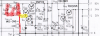
Get the replacement current source built, and subbed in for R211, D209, D208, Q206 & R214.

Your regulator appears to be regulating, but it's operating power is not clean or hum free.

I showed you another example, for the SX-950, where a few mA of regulator operating power
was tapped off of a huge RC ( 1.5kohms, 470uF 63v) filter.
JUST for the concept of the energy needed to operate the regulator.

The SX-1980 uses a constant current circuit that SERVO's OUT the hum. IT FAILS OFTEN. For reasons of design (inadequate).
The replacement pulls the hum level down a conservatively estimated 60 db through it..

This 80v FEEDS the 34v regulator, while the regulator operating power lights up the zener reference which regulates the +34v power.
Zener ripples, output ripples.


This is the first link's pictures, see it for the parts numbers;
depending upon parts choices, it is 2.1mA and good for at least 200 volts.

upload_2021-6-19_20-46-17.png
 
I’m not sure the power supply is causing my hum, but definitely something is different with the positive +80V rail since it has way more ripple than the others.

Took some more measurements to try to get more insights.

I measured the voltages on the JFET source resistor:
R214 upper: Vdc= 0mV, Vac= 0 mV
R215 lower : Vdc= 33.7mV, Vac= 33.5mV

looks like the lower JFET is passing an average of 1.5 mA but the upper is passing nothing.

also I looked at the current through the zeners in parallel with the JFET.

R211 upper: Vdc= 12mV
R213 lower: Vdc= 0mV

I saw one note that said to replace the 24V zeners no matter what (D208/209 and D210/211). I assume that there should be no real DC current through these zeners after power up.

But if there is 12 mV across R211 (Zener path) and 0V across R214 (JFET path), that makes only 120uA (12mV/100 Ohms R211) from this leg that is heading to the collector of Q212.

Thats 10x less than for the lower rail.
 
Last edited:
Markthefixer thanks for the reply, I think I’ve finally come to grips with your comment about the current source not operating properly in my upper rail.

Just wanted to think through this enough to be sure I understand it so that I am solving the root cause rather than just replacing a bunch of parts.

I’m fairly new to this game so I’m being cautious especially when a big beast of an amp (for me) is staring at me.

I keep finding more and more threads that describe yours and echowars designs. This one I had overlooked until a few minutes ago:
https://audiokarma.org/forums/index.php?threads/sx-1980-problems.167959/page-2

Thanks again for your insights and direction since it helps to have inputs from folks who have trod this path before.
 
OK, drilling down...

How / what is a constant current source using a Jfet:
https://www.electronics-tutorials.ws/transistor/fet-current-source.html
enough math to choke a horse, or tickle an engineer pink....

That's Q206, they add R214 as Vrs (about halfway down in the explanation.) to modify the final current.

Now, all would be fine and dandy, EXCEPT Q206 2sk34 is a maximum 30v device. They hand selected those that survived at 50v.

Not good... they were still popping like popcorn

SO.... they added D208 (24v), D209(24v) and R11 (100 ohms) across Q206 to protect it. A 48v clamp.

well, the real world is tough, and these popped (too much) in the real world over the years, so EchoWars did something about it.

Later on, frustrated about custom PC boards, I cobbled up something simple that was easily fabricated from common (perfboard) materials.
Found useful, inexpensive and somewhat common parts to use.
Documented the daylights out of it, and finally set it loose. Including finally, how / where to shoehorn it in on the AWR-154 board

Just think of that circuit as a 2 wire component Q206.

If you get inventive, you will find "CRD" current regulator diodes, which are two leaded packages containing a Jfet wired up as a current source/sink.
They'd be nice to use (we do use them elsewhere where conditions are more benign) but the environment in the SX-1980 is just too hostile.
The replacement circuit's voltage limits are pretty much the transistor's Vceo, and in the realm of 200 to 300 volts with these transistors.
That's why when I listed transistors, I also included Vceo specs for each.


p.s. I stopped counting how many SX-1980's I have worked on when I ran out of fingers, and didn't want to take off my shoes to keep count.
 
Last edited:
I dug a bit more at the replacement parts that are currently on this board.

For the upper Q206 JFET is marked “133” in a To92 package. I can’t find the exact datasheet, but if it is the same die as a NT133, then it’s only a 25V JFET. (maybe this part? https://www.nteinc.com/specs/100to199/pdf/nte133.pdf)

Lower Q207 is labeled as “K34 67C”. Perhaps this is original.


Will educate myself the details of the updated current source design and get started on it.
Many thanks again for the guidance and pointers.
 
There is the factory upgrade to consider, it uses two 18v 500mW zeners in series to make the reference for both pos and neg
K34 jfet looks to be original. There are a few ways to make a ccs, one being the ring of led ckt that was provided to EW in a DIYAudio thread a few years ago. I had one guy put the leds in backwards. There is enough leakage to have the reg operate, but it does not regulate very well and v is out of spec
The other issue is the series pass bjts run pretty damn hot, that is why some remote mount them to the ops heatsinks. It is a fair amount of work
 
Last edited:
Some progress, but now the +80V doesn't come up with a "fast" turnon using the main power switch. Here are the details:

Two steps forward and one step back. I installed the 2mA current source using the "echowars" and "@markthefixer" board layout into my +80V supply. Ripple is now unmeasurable on the +80V rail.

The positive rail comes up just fine when I gradually turn up the voltage using a Variac.
However, the +80V doesn't come up when I flip the switch on at full line voltage!

When I turn-on with the main switch, the voltage across the 35V Zener lingers around 7V and the output voltage wanders around somewhere in the same range. I suspect that turn-on of the voltage rail depends upon the sequence of currents and voltage that kick in when the power switch is flipped. It must be a different sequence depending whether the voltage comes up slow (Variac) vs. turns on fast (main power switch flipped when plugged into the mains).

Question: Have you folks seen this kind of behavior, and if so, how have y'all addressed it?

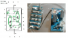
My bill of materials for the current source:
  • PNP upper: KSP92BU
  • NPN lower: KSP43BU
  • 1.2kOhm resistors (2)
  • Green LEDs 568 nm Kingbright, 3mm LED (2) part number WP132XGC (long lead is anode, short lead is cathode)
  • 1 MOhm resistor (1)
A beauty shot is attachedIMG_8488.jpg
 
Are you getting the full 100 volts at the top of C204 (220/160)?
Is the R210 (5.6 ohms) reading the correct value?

What about mitigating / disconnecting the +80v load?

Any old caps left in that section?

It doesn't depend upon any other voltage to come up on.

and no, i have never seen anything like that on all of those i have worked on.
 
Last edited:
R210 is 5.1 Ohms.

I’m getting about 100V on the R210/C204.

There are old caps throughout but I tested for ESR and nothing was suspicious.

If any pre-emptive capacitors should be replaced I assume they would be C216, C218 and possibly C220.

Also after seeing this issue, I changed D212 to the recommended 17V+18V Zeners and there was no change (other than slightly lower Zener voltage on normal operation with the Variac).

Also I disconnected the amplifier boards, no change.

Definitely the current source solved my ripple issue (thanks to y’all for developing that!) but it kicked off this strange startup situation, probably highlighting another component in this unit that is “iffy”.
 
There are old caps throughout but I tested for ESR and nothing was suspicious.

If any pre-emptive capacitors should be replaced I assume they would be C216, C218 and possibly C220.

c216 100uf / 50v across the zener, definitely
c218 10uf / 50v across the hot to the feedback divider, definitely
c220 100uf / 100v output smoothing, i would also.

They are all small caps, in a hot environment. They have far less moisture to lose.
ESR tester read capacitance too?

My ESR meter runs the test at 150 KHz, I don't trust it's good readings, only it's bad.
 
I'm hardly a qualified technician nor an electrical engineer, but my limited experience with electronics this age is that ALL electrolytic capacitors are suspect even if they test OK with a standard test device. Typically those run at lower voltage, and unless you are applying 50 or 100V on those caps you don't know if they hold up at that voltage. My suspicion is that the answer to that question is NO. Old electrolytic caps fail in more than one way, and while the ESR may be OK they may have high leakage at operating voltage.

Replace them all in the PS section, you are going to wish you had if you don't. Erratically operating capacitors do all sorts of strange things even when they test "within tolerance".

I don't trust old zeners either -- my KA-80 blew up twice from zener failures
 
Brief update: I decided to risk it and plug in the power amps and listen for hum. I started up with the variac, the +80V rail comes up fine and and as adamantly experienced and suggested by @markthefixer, the hum is gone.

I tried again with mains voltage and flipping the switch on, and the same weird voltage came up on the +80V rail, starting somewhere around +15V and then after about 15 seconds wandering down just below 0V before I turned it off.

Perhaps during the transient of fast turn-on, maybe the blocking voltage of one of these transistors is being exceeded. The transistors on this rail range from blocking voltage rating of 100V Q210 (2SD712), to 50V for Q208 (2SC945) and blocking voltage of 80V for Q212 (SK3449 replacement part).

I’ll do some more measurements across these three transistors and see if I can gain some insight.
 
Most regulators I worked on were in pretty poor shape, so they got a complete silicon refresh.

That's a pretty motley assortment of transistors. Are the D712 and C945 in the darlington pass element original?
the sk3449 is an 80v 0.4a 0.8w 120MHz 160hfe transistor.
not too shabby compared to the original 2sc1318 at 50v 0.5a 0.625w 200MHz 40-340 hfe transistor
yet I used the (q212) ksc2690a at 160v (or the non-a at 120v) 1.2a 1.2-20W 155MHz 35-320 Hfe
(Q210) mje15032g 250v 8a 50w 30MHz 10-70 Hfe
(Q208) ksc2383 160v 1a 0.9w 20-100MHz 60-320 Hfe

You can see that there are plenty of voltage margins with these 3.

There very much could be a situation where the current feedback transistor gets more Vceo than it can handle, so it latches on, or the leakage is enough to light up (partially) the regulator.

I would STRONGLY suggest getting a much higher Vceo transistor into that position.

I think under normal conditions that the Darlington pass element passes muster, but under abnormal conditions?
 
Last edited:
Back
Top Bottom