• The move to the new server is done. There are some software and database maintenance updates in process. This has us passing the hat around to help out. We appreciate any donations. Seriously, even a dollar helps. The payment page may be found here - https://www.audiokarma.org/support.html

Pioneer SX-1980 hum both channels

I would STRONGLY suggest getting a much higher Vceo transistor into that position.

Awesome! Thanks for the parts suggestion. We are of the same mind, more margin is needed to prevent weird conditions from happening that could kick off unexpected states of these parts that could spell disaster.

Will get some parts and report back. Glad that the hummingbird is quiet now, but still won’t be able to sleep at night until this unit is rock solid on this +80V rail.
 
Just to confirm the measurements of what is going on:

Q212: Vce slow turn-on = +44.9V, fast turn-on = +10.7V
Q208: Vcb slow turn-on = +27V, fast turn-on = +103V!

Q208 looks to be latching on during the fast turn-on. My unit has a 2SC945 (stock?) with a BVcbo of 60V and BVceo of 50V. So this measured value of 103V is way beyond the rating of this part. Yikes!

Warning: The echowars current source mod likely requires updating some other components with higher blocking voltage to ensure they stay within their safe operating area.


Will get some of the recommended transistors and report back. Thanks for all the suggestions and guidance.
 
Warning: The echowars current source mod likely requires updating some other components with higher blocking voltage to ensure they stay within their safe operating area.
.

The echowars current source mod is recommended as PART of a TOTAL REBUILD (all new silicon, e-caps,factory updates etc...)
BUT
YOU weren't gonna jump at that first.

Figured after the hum was stomped out, my word would have a bit more "authority".

Remember, you still have the -80v regulator, the 13v / 8v etc regulators in it to fail.

Callbacks are my wooden stakes, garlic, holy water, silver bullets & such... so I make SURE their odds are terrible.

ONE callback in all these years, the mesh on the gears of a VC tuning cap was one tooth off, and the FM couldn't hit the sub 88 MHz College station.
 
Ok, reporting back my findings. All testing is with the power amplifier boards disconnected.

I replaced Q208 with KSC2383, Q210 with MJE15032G, and Q212 with KSC2690A. Replaced C216, Q212, C222 (original tested low for capacitance), C224 and C218.

I tested after each of these changes and there is no change in behavior. The +80V rail comes up ok when dialing up with Variac, but when switching on fast the rail goes up to maybe 10-15V and then drops to slightly negative.

I removed R226 (1k resistor going to the +34 V darlington base of Q214) and the rail comes up ok with Variac AND with fast turn-on are both OK.

I reconnected R226 and the fast-turn on failed again.

Next I removed power supply pin 9 to remove all the +34V loads. Both Variac slow turn-on AND fast turn-on is OK.

I replaced pin 9 and then pulled some of the loads one at a time. If I just leave the equalizer connected (remove Pins 4 and 5 from flat amp) the positive rail goes up to +15, hesitates there a little and then starts rising up to +80V. When I connect back the flat amp (just reconnecting pin 4 on the flat amp, leaving pin 5 disconnected which goes to the tone control board), the Variac slow turn-on is ok but the fast turn-on FAILS.

It seems like something in the 34V rail is loading the +80V rail enough that it doesn't start reliably. I checked the in-circuit capacitance and ESR of the main +34V caps on each of these auxiliary boards (flat amp, tone and equalizer), but nothing was suspicious.

The +34 rail darlington consists of:
Q216: NTE152 (90V, 4A, 40W)
Q214: NTE194 (180V, 600 mA)

The junctions on these check out ok, but I haven't replace them yet.
The 360 Ohm, 10 Watt resistor checks out ok for resistance.

Seems like something is pulling down the 35V zener voltage and preventing the +80V feedback from starting properly with fast turn-on.

The lower -80V and -34 rails pop up really fast.

So, I don't think my problem was anything to do with Q208, Q210 or Q212, but I can sleep better that there is more voltage margin on that rail.


However, I suspect that something is wrong with Q216/Q214 but I haven't found it yet. I may just shotgun replace them, but don't have any real theory as to what could be going wrong there that's prevent the startup of the +80V rail when I flip the switch.


I just realized that I need to check C301, D301 zener and Q303 since that's on the +34V rail. That's another load on the +34 rail that I haven't examined yet.
 
Last edited:
re: r301 2.2k 1/2w, C301 100uf, D301 13v 0.5w for the protect circuit
that 2.2k resistor is pretty good isolation.

well the +34v line goes out of pin 9 at supposedly 64 mA.
it goes to two places
one
the flat amp AWG-058 pin 4 (back out on pin 5 on b' line) and you will see that many manuals do not have the flat amp board in them.
The flat amp has a 390 ohm resistor with a 330uF capacitor input filter. (but not for pin 5) the flat amp has a 26 mA legend on it.
two
equalizer amp AWF-031 pin 6 in, and has a 40mA legend at it.
the equalizer amp has a 100 ohm resistor with a 220 uf capacitor input filter.

now we go back a bit to the flat amp 34v output on pin 5, the b' line.
That goes to two places.
one
tone amp assy AWG-059, pin 3 in, to a 3.3k ohm 100uF input filter. The back end of this filter is shown as 13v, so with 3.3k, a 21v drop indicates 6.4 mA.
two
the filter assy AWM-119 pin 5.
we got a bit of a gotcha here
The board has two 2sc1313 (a somewhat troublemaker) who's collectors are DIRECTLY connected to the +34v.

That's my vote for shenanigans.... The AWM-119 Q1 & Q2

most of the rest have 1/4 watt resistors in the way.

Assume a shorted filter cap.
34v across 390 ohms 87mA 3 watts into a 1/4 w - zapp
34v across 100 ohms 340mA 11-12 watts into a 1/4w - blooie
34v across 3300 ohms 10mA 0.35 watts... meh - a bit of smoke.
34v across 2200 ohms 1/2w 15mA 0.5 watts on a 1/2 watt resistor. It's normally running at 9 mA (34v in, 13v zener out)
 
I did a little more testing to verify some of the hypothesis. All testing is performed with power amplifier boards disconnected. Also, I removed Q215 (NTE152 which had gain lower than data sheet and also a little leaky 6mA) and replaced with TIP41C (100V, 6A). Status is unchanged: Variac slow turn-on is OK but fast switch-on FAILS.

Here's the data:

During slow turn-on with Variac:
  • R2 is 360 Ohms and has 24V across it (67 mA load).
  • R226 is 1 kOhm and has 1V across it (1 mA load).
That adds up to 68 mA going out of pin 9.
So, it looks like my 34V boards that are driven from the pin 9 of the power supply board (tone board, filter, flat amp, equalizer) are drawing the specified amount of current from the +34 V rail (schematic says 64mA).

I pulled the following boards and check the fast turn-on response.
  • Remove pin 5 of the flat amp (disconnects +34 from the tone control and and filter assembly). Result: fast turn-on FAILS
  • Remove pin 4 of the flat amp (disconnects +34 from the flat amp itself). Result: fast turn-on FAILS
  • Remove pin 6 of the equalizer (disconnects +34 from the equalizer board itself). Result: fast turn-on OK
From the schematic, the equalizer board consumes the majority of the +34V rail current (40mA out of 64mA). The +34V rail goes to both channels through 100 Ohm resistors (so effectively 50 Ohms load). I checked ESR on these filter caps and they seem ok. The NPN transistor junctions look ok and are high resistance collector-to-emitter (Overload on my DMM).

  • Reconnect pin 4 of the flat amp. Result: fast turn-on is OK.
  • Reconnect pin 5 of the flat amp. Result: fast turn-on is OK.
  • Reconnect pin 6 of the equalizer. Result: fast turn-on FAILS.
My conclusion: The load from the equalizer board is the majority of the load, so I suspect that the equalizer board is ok (since total current of 68 mA with slow turn-on is in-spec). I think by just adding extra load from the EQ board, that whatever is wrong with the power supply is causing the +34V rail to be loaded too much and the D212 35 Volt Zener isn't able to kickstart properly during fast turn-on.

Here's a speculation as to what is going on, and y'all can correct me:

During turn-on the constant current source should see enough voltage to kickoff the 2mA current source (with slow turn-on the current source kicks on at about 60V AC input voltage, as observed by the green LEDs).
This 2 mA supplies the base of the Q212 "error amplifier" through Q201 B->E, Q210 B->E, R220 (and shunted through R222 to ground) and R218. Then this current is split between the D212 35V Zener and the +34V darlington driver (Q214/Q216).

I'm suspecting that if pin 9 is too heavily loaded, that the Q214/Q216 are sinking the majority of the 2mA current, and the D212 35V Zener cannot get kickstarted.

The above considers just the DC status, really I'm facing a transient problem. Some contributing factors to transient response are C216 that works keep the voltage across D212 tied to ground during turn-on, and C220 that suppresses the rise of the +80V output rail.

I could try reducing C216 or adding a resistor in series to damp the response, however that may be at the expense of ripple when the voltage kicks off properly.
Basically, I really want D212 to hog the current until the output voltage rises enough for the rail voltage through R22 to sustain the +35V across the zener. I need to prevent any current shunting off to the +34V rail until the +80V supply is high enough.

I'm at a loss on a solution here with this cool 2mA current source. The lower rail works great with the JFET solution. I'm hesistant to switch the upper rail back to the JFET current source since I believe the feedback that it won't be a robust solution.
If you have good ideas about what I'm missing, I'm all ears.

(Edit: I checked the soft start. When the system is operating properly (with a good +80V rail) I hear the relay click maybe 0.2 sec after flipping the switch. The 3.3Ohm, 20 Watt resistor is wired in series with the thermal fuse.)

I appreciate all the guidance on this tricky problem, and thanks for hanging with me through all the long details of my testing.
 
Last edited:
Wow this turned out to be a long thread.
Why are you using the variac?
This way may damage the soft-start TF/3R/(20W) since it is taking way too long for the relay to kick in.
I use the DBT, if it dims within a few seconds, take it off you are okay to go.
You can measure voltages across these R's & calculate all the currents being draw from AWR-154
1) R210,R212 (5R6)
2) R2(360)
3) R3(470)
4)R202(47)
5) R203(3R3)
 
I've characterized the +34V rail (using R2) and under normal (slow turn-on) conditions the load is 68 mA.
For the +80V rail when it comes up properly, looking across R210 (5R2 in my circuit) I see 380mV, giving 73 mA load (both amplifier boards disconnected).

On fast turn-on the +80V supply section pulls around 30 mA (through R210 (5R2) and steadily increases over time before I turn it off. I didn't let it get above 50mA when I just tested.
 
Last edited:
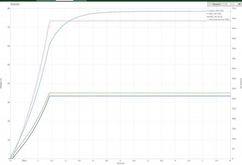
I did some basic circuit simulations of the circuit to understand which component values affect the behavior:
https://www.multisim.com/content/6mcxcduwdvSLFb8qp4d8Wk/pioneer-sx-1980-80v-rail/

I haven't found any way to slow down the +34V rail versus the +80V rail. These two are linked pretty linearly.

I see that selecting C216 affects how fast the +80V and +34V rails come up.

I couldn't cause the circuit to "lock up" like I am observing, but I suspect I'm kicking off some nonlinear behavior that isn't capture in these basic models.

I'm really struggling with this one.
  • I double checked the circuit connections several times (since some of the traces are damaged) on the +80V and +34V circuits.
  • I replaced all the electrolytics and transistors (except for Q214 [NTE194] which tested perfectly fine on the component tester) on the +80V and +34V circuits.
  • I even removed the two ceramic caps and verified their values.

The struggle continues....

Here's a trace of the simulation, showing how the +80V and +34V rails come up together. Not sure if the Zener voltage is realistic or not, since probably depends a lot on the Zener diode model.

 
Last edited:
Time to use a digital scope the 80v unregulated ,80v, 34v zener? And see what’s going on

Unfortunately all I've got is a non-digitizing scope. I may need to find a friend...

I did some checking on the +34V rail going to the protection circuit. Under normal operation, R301 has about 20V across it (10 mA).
Whenever I switch on the system fast, the current changes direction (current is then flowing into the +34V rail, starting at 1mA and then heading to 4mA and then I cut it off).

I then removed R301 to eliminate the load from the protection circuit, and still the same issue is observed. Blech...
 
Have you replaced that zener? Given my experience with smoking amps with shorted zeners, I replace them if there is anything at all odd with a circuit, they can do all sorts of strange things before they go open or short.
 
Yep, I replaced the 35V Zener with a combined series of two 0.5Watt 17V+18V zeners. If I remember correctly, the same behavior was observed with the original zener.

And I triple checked the soft start relay. With fast turn-on, the soft start relay switches just fine.
 
Last edited:
One more wild speculation and then I’m going to sleep on this.
The -34V rail seems to pop up really quick relative to my +34V rail. Could the negative rail be sinking enough current(directly from the +34V rail, not to ground) such that it prevents the positive rail from starting properly?

Tomorrow I’ll start checking the components on the negative rail, starting with C217.
 
A roll call of original and replaced parts CURRENTLY in the +80 and +34v supplies would be good - find what is left that is original (i know I know you tested them as ok) what has ended up in each position.

Personally, I would try a diode in line with R226. I know there's a .6v loss, but as a test, that's not bad.
If it's a reverse current flow through R226, that should choke it out.


The +34 rail darlington consists of:
Q216: NTE152 (90V, 4A, 40W)
Q214: NTE194 (180V, 600 mA)

Those still in there? My searching tends to say YES. (Q214 - ksc2383, Q216 - MJE15032G)

just for giggles, this is NOT a current list - many "gotcha's" in it.
p.s For example,I don't use ksd1616's anymore.


sx-1980 awr-154 c201 0.1 250 cqma 104k 250 mylar
sx-1980 awr-154 c202 0.1 250 cqma 104k 250 mylar

sx-1980 awr-154 c203 3300 35 ach-332 - ceb 3300 50 647-TVX1V332MCD
sx-1980 awr-154 c204 220 160 ach-331 - ceb 220 160 647-TVX2C221MDD
sx-1980 awr-154 c205 220 160 ach-331 - ceb 220 160 647-TVX2C221MDD
or
sx-1980 awr-154 c203 3300 35 ach-332 - ceb 3300 35 647-UPW1V332MHD
sx-1980 awr-154 c204 220 160 ach-331 - ceb 220 160 647-UPW2C221MHD
sx-1980 awr-154 c205 220 160 ach-331 - ceb 220 160 647-UPW2C221MHD

sx-1980 awr-154 c206 0.01 250 agc-001 ceramic
sx-1980 awr-154 c209 100p 50v ccdsl 101k 50 ceramic 100p 50v 505-FKP2100/100/2.5
sx-1980 awr-154 c210 100 10 cea 100 35 647-UPW1V101MPD
sx-1980 awr-154 c211 100 16 cea 100 35 647-UPW1V101MPD
sx-1980 awr-154 c212 100 10 cea 100 35 647-UPW1V101MPD
sx-1980 awr-154 c213 100 6 cea 100 35 647-UPW1V101MPD
sx-1980 awr-154 c214 100p 50v ccdsl 101k 50 ceramic 100p 50v 505-FKP2100/100/2.5
sx-1980 awr-154 c215 100p 50v ccdsl 101k 50 ceramic 100p 50v 505-FKP2100/100/2.5
sx-1980 awr-154 c216 100 50 cea 100 63 647-UPW1J101MPD1TD
sx-1980 awr-154 c217 100 50 cea 100 63 647-UPW1J101MPD1TD
sx-1980 awr-154 c218 10 50 cea 10 50 647-UPW1H100MDD
sx-1980 awr-154 c219 10 50 cea 10 50 647-UPW1H100MDD
sx-1980 awr-154 c220 100 100 cea 100 100 647-UPW2A101MHD
sx-1980 awr-154 c221 100 100 cea 100 100 647-UPW2A101MHD
sx-1980 awr-154 c222 100 50 cea 100 63 647-UPW1J101MPD1TD
sx-1980 awr-154 c223 100 50 cea 100 63 647-UPW1J101MPD1TD
sx-1980 awr-154 c224 100 50 cea 100 63 647-UPW1J101MPD1TD
sx-1980 awr-154 c225 100 50 cea 100 63 647-UPW1J101MPD1TD
sx-1980 awr-154 c226 0.047 150 agc-009 ceramic>film 0.047 400 667-ECQ-E4473KF
sx-1980 awr-154 c227 0.047 150 agc-009 ceramic>film 0.047 400 667-ECQ-E4473KF
sx-1980 awr-154 c228 0.047 150 agc-009 ceramic>film 0.047 400 667-ECQ-E4473KF
sx-1980 awr-154 c229 0.047 150 agc-009 ceramic>film 0.047 400 667-ECQ-E4473KF
sx-1980 awr-154 c301 100 16 cea 100 35 647-UPW1V101MPD
sx-1980 awr-154 c302 100 16 cea 100 35 647-UPW1V101MPD
sx-1980 awr-154 c303 47 16 cea 47 35 647-UPW1V470MED1TD
sx-1980 awr-154 c304 0.047 400 agc-009 ceramic>film 0.047 400 667-ECQ-E4473KF
sx-1980 awr-154 c305 10 16 cea 10 50 647-UPW1H100MDD


sx-1980 awr-154 r101 3.3 ohm 20w can-019 sq w.w.
sx-1980 awr-154 r102 3.3k 2w mox - relay coil
sx-1980 awr-154 r202 3.3 ohm 1/2 W cf 660-CF1/2C3R3J
sx-1980 awr-154 r203 47 ohm 3w mox
sx-1980 awr-154 r209 39 ohm 1/2 W cf
sx-1980 awr-154 r210 5.6 ohm 1/2 W cf 660-CF1/2C5R6J
sx-1980 awr-154 r212 5.6 ohm 1/2 W cf 660-CF1/2C5R6J
sx-1980 awr-154 r220 59k 1/2 W metal film
sx-1980 awr-154 r221 59k 1/2 W metal film
sx-1980 awr-154 r222 51k 1/2 W metal film
sx-1980 awr-154 r223 51k 1/2 W metal film
sx-1980 awr-154 r301 2.2k 1/2 W cf
sx-1980 awr-154 r308 3.3k 2w mox - relay coil
sx-1980 awr-154 r309 3.6k 1/2w cf


sx-1980 awr-154 Q201 c945a to-92 +13.5v darl driver 512-KSD1616ALBU
sx-1980 awr-154 Q202 c945a to-92 +15.5v feedback 512-KSD1616ALBU
sx-1980 awr-154 Q203 d712c TO-220 +13.5v series pass 863-MJE15032G
sx-1980 awr-154 Q204 c945a to-92 +8v darl driver 512-KSD1616ALBU
sx-1980 awr-154 Q205 d325r TO-220 +8v series pass 863-MJE15032G
sx-1980 awr-154 Q206 2sk34 to-92 +80v cc startup
sx-1980 awr-154 Q207 2sk34 to-92 -80v cc startup
sx-1980 awr-154 Q208 c945a to-92L +80v darl driver 512-KSC2383YBU
sx-1980 awr-154 Q209 a628a to-92L -80v darl driver 512-KSA1013YBU
sx-1980 awr-154 Q210 d712a TO-220 +80v series pass 863-MJE15032G
sx-1980 awr-154 Q211 b682c TO-220 -80v series pass 863-MJE15033G
sx-1980 awr-154 Q212 c1318 to-126 +80v feedback to-126 512-KSC2690AYS
sx-1980 awr-154 Q213 a720 to-126 -80v feedback to-126 512-KSA1220AYS
sx-1980 awr-154 Q214 c869 to-92L +34v darl driver 512-KSC2383YBU
sx-1980 awr-154 Q215 a628 to-92L -34v darl driver 512-KSA1013YBU
sx-1980 awr-154 Q216 d325 TO-220 +34v series pass 863-MJE15032G
sx-1980 awr-154 Q217 b536 TO-220 -34v series pass 863-MJE15033G

sx-1980 awr-154 Q301 a872a to-92 o/c prot input 512-KSA1013YBU
sx-1980 awr-154 Q302 c1438 to-92 >to-126 relay driver 512-KSC2690AYS
sx-1980 awr-154 Q303 pa3004 8 sip prot chip

sx-1980 awr-154 D212 35v 0.5w 512-1N5247B 17v 0.5w 512-1N5247B
sx-1980 awr-154 D212aa 512-1N5248B 18v 0.5w 512-1N5248B
sx-1980 awr-154 D213 35v 0.5w 512-1N5247B 17v 0.5w 512-1N5247B
sx-1980 awr-154 D213aa 512-1N5248B 18v 0.5w 512-1N5248B
sx-1980 awr-154 D207 6v 0.5w 512-1N5234B 512-1N5234B
sx-1980 awr-154 d301 13v 0.5w 512-1N5243B 512-1N5243B
sx-1980 awr-154 d214 1s2473 512-1n4148
sx-1980 awr-154 d215 1s2473 512-1n4148
sx-1980 awr-154 d216 1s2473 512-1n4148
sx-1980 awr-154 d302 1s2471 512-1n4148
sx-1980 awr-154 d201 sib01-04 400v 1a 512-1n4004
sx-1980 awr-154 d202 sib01-04 400v 1a 512-1n4004
sx-1980 awr-154 d203 1s1885 100v 1a 512-1n4004
sx-1980 awr-154 d204 1s1885 100v 1a 512-1n4004
sx-1980 awr-154 d205 sib01-04 400v 1a 512-1n4004
sx-1980 awr-154 d206 sib01-04 400v 1a 512-1n4004

sx-1980 awr-154 S1 spdt 48v surge relay just open and clean
sx-1980 awr-154 S2 dpdt 48v prot relay just open and clean
sx-1980 awr-154 S1 spdt 48v to 24v!!! surge relay 653-LY1-0-DC24
sx-1980 awr-154 S2 dpdt 48v prot relay 653-MY2-02-DC48
sx-1980 awr-154 tf1 aex-001 229 deg thermal fuse 10a/15a 250vac 526-nte8108


current source pos
npn npn transistor 522-ZTX696B
pnp pnp transistor 522-ZTX796A
npn npn transistor 512-2N5551BU or ksp42??
pnp pnp transistor 512-KSP92TA
1.2k 1.2k 1/4-1/8w 660-MFS1/4LCT52R122J
green led green led 604-WP132XGC
1 meg 1 meg 1/4-1/8w 660-MFS1/4DCT52R1004


current source neg
npn npn transistor 522-ZTX696B
pnp pnp transistor 522-ZTX796A
npn npn transistor 512-2N5551BU or ksp42??
pnp pnp transistor 512-KSP92TA
1.2k 1.2k 1/4-1/8w 660-MFS1/4LCT52R122J
green led green led 604-WP132XGC
1 meg 1 meg 1/4-1/8w 660-MFS1/4DCT52R1004
 
Thanks for the suggestions. I've changed out all the electrolytics in the +80/+34V rail. The only silicon that I haven't changed is Q214 (NTE194) and the diode D214. When I wrap this up succesfully, I'll summarize with all the replacements that I used.

I think I'm getting closer, here goes:

I disconnected the load from the -34V rail (removed pin 11 from the AWR154 board). Now fast start-up is OK.

My working hypothesis:
  • Observation: The turn-on speed of the +80V/+34V and -80V/-34V rails are very different. The -80/-34V rails are really fast (< 1 second), while the +80V/+34 rails are slow (several seconds).
  • Modeling: The key parameters that affect the turn-on speed are: C216/C217 capacitance (the electrolytic capacitor across the Zener diode) and the current value supplied by the current source.
  • Statements of fact:
  1. I replaced the upper rail (+80V/+34V) with the solid 2mA @EchoWars current source built in @markthefixer style.
  2. I kept in place the JFET current source on the lower rail.
  • Working hypothesis: The fast turn-on of the lower -34V rail is loading the +34V rail. The loading on the +34V rail prevents the +35V from appearing on the Zener, and the upper rail voltage cannot rise sufficiently to kick-start the regulator and the regulator feedback.
So far, I have been following my mentor's mantra of "fix it first, upgrade it only when it's working".
Now, I have determined it is now the time to break the rules and upgrade the lower -34V rail with the 2mA echowars current source in MTF-style, add new transistors and new electrolytic capacitors. I will upgrade the transistors to ensure plenty of voltage margins, to prevent any blocking voltages from being exceeded with this new modification.

Quick summary: The upper and lower rails should be matched in transient performance, to prevent one rail from loading down the other rail and prevent it from starting properly.
Lesson (not to be overdone, though): This may be a rare case where implementing fixes a piece at a time can cause problems.


Now on to heating the soldering iron, cleaning the magnifying glass and staring deeply into the bright inspection light.
 
Ok, so took a deep breath, dove in and now my hypothesis was confirmed: One must provide similar currents from current source on the positive and negative rails to ensure reliable startup of both power rails.

Of course against typical best judgment, I wholesale replaced all the transistors and capacitors. I dim-bulbed (starting with 40W, then to 100W) and Variac'ed the heck out of this when bringing it up.

Now, all is copacetic and both positive and negative rails startup reliably. This SX-1980 sounds really good and the weight of it it now keeps my workbench from flying up.

Y'all are awesome for providing these great resources to lowly apprentice techs like me to solve tough problems.
Especially thanks a lot @markthefixer, I hope I did you proud on this one.

-kmatch


-------------------------------------
For posterity, here is a collection of my replacement parts:


Schematic ID Description Part number
Modification: “echowars” current source PNP transistor KSP92BU
Modification: “echowars” current source NPN transistor KSP43BU
Modification: “echowars” current source 1.2 kOhm resistor MFS1/4LCT52R122J
Modification: “echowars” current source Green LED WP132XGC
Modification: “echowars” current source 1 MOhm resistor MF1/4CCT52R1004F

Q210 "NPN 250V, 8A, TO220" "MJE15032G, OnSemi"
Q208 "NPN 160V, 1A, TO-92" "KSC2383YTA, OnSemi"
Q212 "NPN, 160V, 1.2A, TO-126" "KSC2690AYSTU, OnSemi"

Q216 "NPN 100V, 6A, TO-220" "TIP41C, STMicro"
Q214 "NPN 160V, 1A, TO92" KSC2383YTA OnSemi

D212A 18V zener BZX55B18-TAP
D212B 17V zener 1N5247BTR

C218 10uF/100V capacitor UVY2A100MDD
C216 100uF/50V capacitor ESL107M050AGMAA
C220 100uF/100V capacitor ESH107M100AH4AA
C222 100uF/50V capacitor ESL107M050AGMAA
C224 100uF/50V capacitor ESL107M050AGMAA

Q211 "PNP 250V, 8A, TO220" "MJE15033G, OnSemi"
Q209 "PNP 160V, 1A, TO92" "KSA1013YTA, OnSemi"
Q213 "PNP 160V, 2.5A, TO-126" "TTA004B,Q Toshiba"

Q217 "PNP 100V, 6A, TO-220" "TIP42C, Toshiba"
Q215 "PNP 160V, 1A, TO92" "KSA1013YTA, OnSemi"

D213A 18V zener BZX55B18-TAP
D213B 17V zener 1N5247BTR

C219 10uF/100V capacitor UVY2A100MDD
C217 100uF/50V capacitor ESL107M050AGMAA
C221 100uF/100V capacitor ESH107M100AH4AA
C223 100uF/50V capacitor ESL107M050AGMAA
C225 100uF/50V capacitor ESL107M050AGMAA
R212 5.6 Ohm (1/2 Watt)


IMG_8732.jpeg


IMG_8733.jpeg
 
We all learned a few things too!! :thumbsup:

My own practice of treating the power supply as an integrated unit (while expressing the "fix it first, THEN upgrade it" philosophy)
masked a rather ugly propensity to misbehave.

I don't even TRY to power such a powerful unit up unless I have full confidence that nothing will blow up.
I approach it like EVERYTHING is bad, and I have to prove that each component is up to doing it's assigned job.
Course I KNOW that the stuff is coming to me in a broke and abused state.
 
Back
Top Bottom