• The move to the new server is done. There are some software and database maintenance updates in process. This has us passing the hat around to help out. We appreciate any donations. Seriously, even a dollar helps. The payment page may be found here - https://www.audiokarma.org/support.html

Pioneer Sx-434 - no left channel and hum

Almiscarado

Member
Hi there!

This is, or I hope it to be, my first vintage amplifier repair. I bought this unit very cheap, it was almost given, but the PO declared it as defective.
I assumed it could be possibly a nice project to learn. It is in no good cosmetic shape, and two knobs are missing and/or were cut, so the value of this unit should be just for learning and if all goes well, garage use later on.

First checks: the unit power up, but there is only sound on right channel. Left channel has no sound, just a bit of hum.
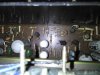
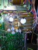
Opened it up and visual check gave me suspicions of one bad ceramic capacitor on the PS board (check image please), and a burned resistor on the main board. It should be hard to identify the value of this resistor...
IMG_20160505_093333.jpg

IMG_20160505_093433.jpg
To a newbie one this, what would be the first things to check? Replace these two components? I am new to audio repair, but have some electronic background (HAM radio, etc).

All the help will be usefull!

Thanks,
Sergio
 

Attachments

  • IMG_20160505_093333.jpg
    IMG_20160505_093333.jpg
    85.7 KB · Views: 69
Register to hide this ad
Hi, first off, you'd like to download the corresponding service manual. I checked out and luckily for you, it is available. You'll need to open an account at hifiengine to do so.

http://www.hifiengine.com/manual_library/pioneer/sx-434.shtml

The service manual will allow you to identify the specific components you pointed out visually, their values, and their relation with the surrounding circuitry. Changing a burned out resistor for a new one is not a good idea. Since resistors get destroyed for a reason you'd need to find this out first (usually bad associated transistors or voltage regulators).

Also, ideally, your multimeter should be able to read capacitor values, otherwise you'd be guessing about them.

Report back after finding in the schematics the bad resistor in the picture you posted.
 
Hi there! Thanks for the help!

I downloaded the manual, and found out the resistor is R19 - 150 of 750K and the ceramic condenser on the PS board is 0.01 - 150v.
How to determine what made the resistor burn, I must trace where? Sorry about needing so much help...

Thanks,

Sergio
 
Sorry, resistor is R79 - 150 :)

It sits between another resistor R81 of equal value and a transistor Q16 - 2SC1318-R or Q
 
the cap is a noise suppressor for one of the diodes .. unit will work without it but it is best to replace it ..also check the diodes .
 
That's perfect and easy to confirm then :) Can wait to get home and test... I know I'll be a bit confused with the transistors, but will try to paste here my measures... :)
 
Maybe I am doing something wrong, but the diodes on the bridge: I get values on both sides of them, I should get just from one, right' could it be because they are soldered on the board?
 
meter on diode test ..black lead to striped end red to other end .expect a reading of around 570mv 620mv ..
swap leads over expect no reading .
all this with no power on .unit unplugged from the wall .
 
Hi Pete,

i did that and I get readings on both directions... errr... bad capacitors in series could do this?

And have been checking voltages and ,sorry about that, I was checking on headphones and got confused. I have sound on Left channel, the Right one is the one that has no sounds, just some hum.
And found out that there are 10v going to that side of the output (point 24), should read 0 volts like on the other side on point 27... Where could this come from...

(thank you all for the help!)
 
Last edited:
well if one side works power supply must be working .
you need to be taking the transistors that were already mentioned out of circuit for testing . one or more appear to be faulty .
 
looks like R73, the vertically mounted resistor, has a melted lead. If Q16 shorted or turned fully on, then full power supply current would flow through R73 and 79. Makes me wonder about the condition of STV3 - maybe it failed open circuit? Kudos on picking a great first project. Inexpensive and easy to work on but sounds and looks great. It will be hard to let go once you fix it.
 
If you're getting sound from one channel, then the diodes are ok as the power supply is working. If memory serves, the 434 doesn't use a protection relay. It also sounds like you have a bad output transistor or two on the bad channel.
 
Most transistors gave normal results just testing Emitter to Base and Base to Emitter (still soldered on board), except Q15 that gave me from one side to the other of Emitter and Base a normal value of 700 and to the other way(should be none) gave a 1800 result. Could this be the single culprit?
I also saw that R73 resistor, but although it doesnt look good it measured (on board) normal value. I will change it anyway.

Further testing would require removing transistors from board? Any easy way to test STV3 on board? It should act like a diode, right?

Thanks for all the help, and you can notice I am still too much of a newbie, but with your help I might get through this :)

(and sorry about my poor written english, it is not my native language)
 
Here are my readings on Q16:
Q16 - 2sc1318
B - C -> 0
C - B -> 700
E - B -> 700
B - E -> 0
C - E -> 23
E - C -> 23

Do these sound normal?

and on Q17:

Q17 - 2sc1318
B - C -> 0
C - B -> 940
E - B -> 750
B - E -> 0
C - E -> 0
E - C -> 730

Quite different, what could I be looking at here?

Best regards,

sergio
 
Q15 - 2sc1318
B - C -> 0
C - B -> 700
E - B -> 730
B - E -> 1800
C - E -> 820
E - C -> 0

These results are quite different from the others, is this transistor defective?

Kind regards,
 
Back
Top Bottom