• The move to the new server is done. There are some software and database maintenance updates in process. This has us passing the hat around to help out. We appreciate any donations. Seriously, even a dollar helps. The payment page may be found here - https://www.audiokarma.org/support.html

Pioneer Sx-434 - no left channel and hum

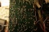
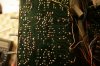
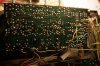
Your description doesn't match your pictures.
R70 burned
R78 burned
R80 new
Q15 removed
Q17 removed
Q19 removed

I can't see what you've done near the edge of the board on the good side. Why did you fiddle with that? Does it still work?

You would probably get more attention in the Pioneer forum. Not sure how to get it moved - you might have to start a new thread?
 
Last edited:
Hi there!

Yes, i got confused and replaced a transistor on the good side. It is working, at least last time I tried it.
Now about the bad side, I got a bunch of transistor replacements, I was thinking of changing all these transistors:

Q15, Q19, Q11 (originally is a 2SA725, I got an equivalent BC259), Q13, Q17 and Q21.

I will also replace burned resistors with proper replacements, would this be safe?

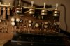
I also built a lamp tester...

Please let me know If I should do these changes :)

Best,

Sergio
 
Here are the original parts, please tell us what you plan to install. Also, this is the first time Q11 and Q13 have been mentioned. Do you think they are bad? Finally perhaps Q23 should be replaced - you've burned resistors on both the positive and negative rails of this channel, so Q23 probably took a hit.
Q11, 2SA725G, ?
Q13, 2SA725G, ?
Q15, 2SC1318, ?
Q17, 2SC1318, ?
Q19, 2SA720R, ?
Q21, 2SD313D, ?
Q23, 2SB507, ?
 
Last edited:
Most are the same part, only 2SA725 was substituted by BC259 and 2SB507 by BD242C, they were sold to me like beeing equal alternatives, do you agree on that?
Should I start soldering the new components?

Kind regards,

Sergio
 
I've filled in your transistor list with the parts you plan to install. Is that correct? I'm not familiar with BC259 or what the pinout is - you'll have to make sure its installed correctly. I'm also not familiar with BD242 but an internet search showed that it is a good replacement and has the same pinout as 2SB507. Unless anyone else sees a problem, I'd say you can solder the new parts. But make it look prettier than the pictures above. If you soldered the parts from the top of the board, then that explains why it looks so bad. Never do that. A bad solder joint in the wrong place can cause parts to burn up.

When you've installed the parts, take close-up pictures top and bottom and post them. Include a picture of your dim bulb tester. Don't apply power until we've had a chance to check things out.

Q11, 2SA725G (PNP), replace with BC259
Q13, 2SA725G (PNP), replace with BC259
Q15, 2SC1318 (NPN), replace with 2SC1318
Q17, 2SC1318 (NPN), replace with 2SC1318
Q19, 2SA720R (PNP), replace with 2SA720
Q21, 2SD313D (NPN), replace with 2SD313
Q23, 2SB507 (PNP), replace with BD242C
 
Last edited:
So after a lot of time, I finnally got the time to solder :)
Everything went well, apart from my ugly soldering skills. Q23, on board, does not give equal results to the 2SB507 on the other side... can this mean trouble?

Here are the photos, hope you can spot any errors... and thanks again for the help!

IMG_5878.JPG IMG_5877.JPG IMG_5878.JPG IMG_5876.JPG IMG_5875.JPG IMG_5874.JPG IMG_5873.JPG
 
be a bit more specific as to what is different like voltage readings base collector and emitter .
another thing when replacing anything and the solder points are close together i check with meter my for any short circuits .. saves lots of time later and also burned up parts .
 
Hmmm the Q23 that was onboard was a Sanyo B514, is this equivalent to the 2SV507? On the good channel there is one of these Sanyo.
Could this mean I bought the wrong part?

I still did not try to power it up untill I figure out all is fine...
 
2sb514 50V, 2A, 20W, 8MHz
2sb507 60V, 3A, 30W, 8MHz
its ok to go higher voltage and wattage but never go lower unless it was well over specked to start with then it might be ok .
 
And today I got a bit sick of waiting and in a moment of weakness I powered it up. The 100w bulb got just a tiny tiny bit on - The good channel still works fine, the bad channel still hums a bit and gives no sound.
This time nothing got burned... so... back to first step? :(
 
Did you get the receiver working??!! I have the same issue same area of pre amp. Left channel is fine, right is dead with all inputs FM etc.. I can solder and have a DMM but I am no EE.

It did not stop all at once but sounded weird a few times when first turned on - like a dirty phono needle which I checked. When it went out, a few smacks made it come on, then went dead. Pulled the cover and probed the suspect area with the trusty chop stick and it worked a a few split seconds then died. No blown fuses, no apparent burnt resistors and all resistors test okay, checked for bad solder joints and cracks on the PCB.. I get a signal right up to the same point as yours was working on both channels when taking voltage readings. I am replacing the 2SC1318 that I suspect when I get a few BC327 Q when they arrive and pray that works..

Maybe it is the caps in that area?? I did re- cap the big filter caps last week. It sounded sweat too. I am bummed...
 
Last edited:
Back
Top Bottom