• The move to the new server is done. There are some software and database maintenance updates in process. This has us passing the hat around to help out. We appreciate any donations. Seriously, even a dollar helps. The payment page may be found here - https://www.audiokarma.org/support.html

Pioneer SX-590 restoration

bitomaxsp

Member
Got my first broken Pioneer recently. Before that i didn't even know AK is exist :) I started googling restoration project to see what people are facing with while restoring SX-580/590 series. Finally i ended up here and decided to make a thread.

I got 590 with complains that left channel has hums. Also no side panels. Scratches all over the body. Someone tried replacing STKs but very not professionally. Also touched FETs (tried to solder them or replacing, who knows). Anyhow, i powered it up and attached my speaker. Checked both channels and it seems hums in both of them. Not sure about at which frequency since i tried usual music.

Then i decided to check PSU voltages. 13.6 was okay. But 41.7V was 7V!. I am like: hmmmm. I postponed.
Then when i had time again, i decided to debug a bit. Warmed up amp a bit and 41.7 bus was already 13V. The more consumers i removed from that bus the more voltage has grown. Nothing pointed to bad transistor. It was original (opposed to 13V which was already changed). I solder it out and omg) transistor was a diode between collector and emitter. Check all the PSU caps, they lower than needed.

Oh! The main thing! Voltage on STKs power supply is symmetric and 29V(-29V).
The one that should be 1.2(-1.2)V is 0.8 and -0.8. Not sure it good or not, but it was with bad PSU though. I'll recheck it once i'll restore the PSU.

So far i have some stuff on order and continue when it arrives.

Also I ordered 10 pieces of STK-0050 replacements from this thread: https://audiokarma.org/forums/index.php?threads/stk-0050-replacement-for-sx-780-and-others.721181
I only need 2 of them.
 
Last edited:
Register to hide this ad
So there was some progress on this.

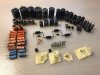
Here is my recap list for 590:

Power:
2SC945A -> KSC2383
2SC1384 -> KSC2690AYS
2SA733 -> KSA1013Y (is a high current PNP)
2SD712 (DB243C) -> MJE15032G


mz140
512-1N5244B Fairchild 14 V, 0.5W Zener x2

mz130
512-1N5243B Fairchild 13 V, 0.5W Zener x2

C403, C404, C406: 220uF/50V -> ELXY630ELL221MK20S x3
C405: 330uF: EKYA630ELL331MJ25S
C407: 47uF/16V -> ELXZ500ELL470MFB5D
C408: 100uF/25V -> EKYB101E101MJ20S
C413, C414: 15000uF: UVR1V153MRD x2
C415: 220uF/35V -> ELXY630ELL221MK20S


C416: 2.2uF/50 -> UKL1H2R2KDDANA

Protect:
C501: 1uF/50 -> UKL2A010KDD1TD
C502: 47uF/25 -> ELXZ500ELL470MFB5D
C503, C504: 10uF/25 -> UKT1E100MDD1TD x2
C505, C506: 0.47uF/50 -> MKP2D034701M00KSSD x2
D501 MZ-022: 1N5251B


Main amp:
C301, C302: 2.2uF/50 -> UKL1H2R2KDDANA x2
C309, C310: 22uF/10 -> UPW1A220MDD x2
C311, C312: 47uF/35 -> UKL1H470KPD1TA x2
C313, C314: 100uF/10 -> UKL1H101KPD x2
C329, C330: 10uF/16 -> UKT1E100MDD1TD x2
C331, C332: 3.3uF/50 -> UKL1H3R3MDD1TA x2
C333, C334: 3.3uF/50 -> UKL1H3R3MDD1TA x2
C335: 47uF/50V -> ELXZ500ELL470MFB5D
C336: 47uF/16V -> ELXZ500ELL470MFB5D
R315,316,317,318, -> 100 Ohm 2%
SC1222 -> KSC1845FTU


Phono:
C201, C202: 2.2uF/50 -> UKL1H2R2KDDANA x2
C207, C208: 47uF/25 -> UKL1H470KPD1TA x2
C209, C210: 100uF/10 -> UKL1H101KPD x2
C211, C212: 2.2uF/50 -> UKL1H2R2KDDANA x2


C219: 47uF/50 -> UKL1H470KPD1TA
C221: 10uF/16 -> UKT1E100MDD1TD


Tuner:
C122: 4.7uF/35V -> UKL1H4R7MDDANA
C124: 1uF/50V -> UKL2A010KDD1TD
C125: 47uF/16V -> ELXZ500ELL470MFB5D
C129: 1uF/50V -> UKL2A010KDD1TD
C132: 4.7uF/35V -> UKL1H4R7MDDANA
C133: 330uF/16V -> EKYA630ELL331MJ25S
C138: 1uF/25V -> UKL2A010KDD1TD


C131, C143: 220uF/16V (power) -> EKZH160ETC22111D x2
C141, C142: 1uF/50 -> UKL2A010KDD1TD x2
C150, C151: 0.47uF/50V (signal FM, 5mm) -> RFS50VR47ME3 x2
C156: 10uF/16V -> UKT1E100MDD1TD (audio signal)
C158: 22uF/16V -> ESMG160ELL220ME11D


C164: 220uF/6V -> EKZH160ETC22111D
C165: 4.7uF/35V -> UKL1H4R7MDDANA
C167: 3.3uF/50V -> UKL1H3R3MDD1TA


C515: 220/6.3 (axial) -> MAL202134221E3

Initially I recapped only PSU and lifted all all the consumers to avoid burning transistors since the first investigation showed that 41V was 7V :) My AC voltages on transformer was a bit higher than expected which led to higher DC voltages, so i had to replace R401 (33Ohm) with 200Ohm same wattage. Then my DC went almost in the park where they should be. SM also gives voltages under full load, so i simulated full load on all lines and made sure voltages are in rages, and they were in fact. Then i decided to recap the AMP part and replace all the diodes with 4148. I didn't touch Zeners, i only tested them in the current range 2-20mA and they were fine.

After AMP part was done, I switched back all the consumers and installed 1kOhm resistores insted of STK and powered up on DBT. Went well. PSU voltages were good. Measured voltages on STK, not good. They were different between channels. So i had to replace some transistors and then voltages became ok.

Then i installed STK and measured voltages. They were right on the spot as in SM (not on DBT already). I supplied some 1klHz tone and listened in the headphones. No buzzing as it was before.

I made a mouser order for STK replacement and now i waiting. Already have 10 PCBs to replace STKs.


After recapping PSU I tested
 
If you increased R401 to make the DC voltages match you have screwed up / strangled the voltage regulators and ripple killer circuits. Put a 33Ω resistor back in for R401. That is like decreasing your cars top speed by installing a skinny fuel line. Strangling the supply to a voltage regulator will cause it to fall out of regulation under dynamic load. 33Ω is intended to be a very slow blow fusible resistor, on the schematic, note the triangle with the ! in it by R401.
Higher AC on the transformer secondaries is not a problem, it is a side effect of vintage equipment operating on today's slightly higher ac line voltages. It will cause higher unregulated DC voltages, that is not a problem either. The exact correct DC regulated supply voltage is less important than that it is a steady voltage with minimal ripple. ±10% from "spec" is most likely fine for a regulated supply. The 41.7v supply is driven by the Q402 ripple killer circuit, it is not a voltage regulator, per se.
 
If you increased R401 to make the DC voltages match you have screwed up / strangled the voltage regulators and ripple killer circuits. Put a 33Ω resistor back in for R401. That is like decreasing your cars top speed by installing a skinny fuel line. Strangling the supply to a voltage regulator will cause it to fall out of regulation under dynamic load. 33Ω is intended to be a very slow blow fusible resistor, on the schematic, note the triangle with the ! in it by R401.
Higher AC on the transformer secondaries is not a problem, it is a side effect of vintage equipment operating on today's slightly higher ac line voltages. It will cause higher unregulated DC voltages, that is not a problem either. The exact correct DC regulated supply voltage is less important than that it is a steady voltage with minimal ripple. ±10% from "spec" is most likely fine for a regulated supply. The 41.7v supply is driven by the Q402 ripple killer circuit, it is not a voltage regulator, per se.

Hi Merlynski. Thank you for you reply. I didn't know all you have described. I'll revert my changes wrt to R401 and do the PSU voltage measurements and post it here. I agree with your car speed analogy, but an quite new to vintage restoration and my reasoning was that voltages should match quite precisely :) I tried googling what is acceptable voltage tolerance and could find any info i could trust unfortunately. IIRC my initial voltages on 33Ohm was off less than 10%. Any way let me try to revert the changes.

Thanks for help once again.
 
You are welcome.
The ripple killer looks much like a voltage regulator circuit at first, but its primary function is different. If you look at the circuit you will see there is not a separate feedback path from the output (emitter Q402) to a voltage correction element. The feedback path is the BE junction of Q402, as well as the output. The 'reference' element for that circuit is C406. Any attempted voltage change at the emitter of Q402 will cause the current through the BE junction to change, which the increases or decreases the collector current to compensate, killing the ripple.
The 'acceptable' voltage tolerance of a power supply depends on the design of the supply regulator and the needs and design of the circuit it is powering. ±10% is a 'collective wisdom' rating for DC (regulated/ripple kill) supplies on Pioneer vintage gear. My personal liking is for ±5% on regulated supplies, and ±10% on ripple killers, but I don't expect normal production tolerances to be that way. In fact, I would not worry about a 20% voltage tolerance on a ripple killer if the ripple is good and the circuit it powers is behaving correctly. I have helped another AK member 'blueprint' his regulated power supplies, but is is a finicky process requiring a lot of time and a large selection of values of 1% resistors. Or a modification to add a pot to make it adjustable.
 
Last edited:
You are welcome.
The ripple killer looks much like a voltage regulator circuit at first, but its primary function is different. If you look at the circuit you will see there is not a separate feedback path from the output (emitter Q402) to a voltage correction element. The feedback path is the BE junction of Q402, as well as the output. The 'reference' element for that circuit is C406. Any attempted voltage change at the emitter of Q402 will cause the current through the BE junction to change, which the increases or decreases the collector current to compensate, killing the ripple.
The 'acceptable' voltage tolerance of a power supply depends on the design of the supply regulator and the needs and design of the circuit it is powering. ±10% is a 'collective wisdom' rating for DC (regulated/ripple kill) supplies on Pioneer vintage gear. My personal liking is for ±5% on regulated supplies, and ±10% on ripple killers, but I don't expect normal production tolerances to be that way. In fact, I would not worry about a 20% voltage tolerance on a ripple killer if the ripple is good and the circuit it powers is behaving correctly. I have helped another AK member 'blueprint' his regulated power supplies, but is is a finicky process requiring a lot of time and a large selection of values of 1% resistors. Or a modification to add a pot to make it adjustable.

Hello :)
I out back 33Ohm and measured main voltages. To me is seems a bit high, but could you also please check?
Conditions: Aux, No signal, Volume min. Tone on centers.

Q402 E: 48.9V C: 51.0V B:49.5V
C406+: 26.4V
Q401: B: 13.9V E: 13.4V
C416 -: -30V
D401 (catode): 52.2V


Q501: E 13.2V C: -21.9V B 13.2V
Q502: E C 26.4V B -21.9V
 
On the schematic Q402 has about 3vdc from C to E, your measurements show about 3vdc from C to E, that looks to me like Q402 is biased correctly.
The schematic indicates the voltage drop across R401 (33Ω) is about 0.9vdc, your measurements indicate the drop is 1.2vdc, so the current through it is 36mA. Schematic shows Q402 emitter current as 26mA.
The circuits it powers are small signal class A transistor amplifiers that are capacitor coupled between the stages, and the differential amp stages at the front of the power amp section.
Unless those stages are misbehaving, which you have not indicated, the 'extra' voltage, IMO should not be a problem.
Is the dc offset about 0vdc at fuses FU3 and FU4? If that is less than +/-100mV check for any hum from the speakers now?
 
Last edited:
Q502 E voltage is missing, please post.
Hi merlynski,

Q502 : -21.5V Which seems fine to me.

Also measured, Vdc across FU3, FU4. It's about 4-5mV stable. I tried hooking speakers up, though i didn't hear any sort of hum. On contrary, sound is quite clear to me.

I also compared other voltages with schematic, they seem to correlate. I'll proceed with replacing Q301,Q302 (2SA798). I already have matched pairs of KSA992.
Also will start assembling STKs replacemets.
 
Q502 E voltage is missing, please post.

Hi merlynski, I was a bit uncertain that I correctly listened for the hum. I checked FU3/4 again, both has 3-4mVDC offset on them.
But if there is no signal on aux and I add volume I hear increasing hum. I stops increasing on 3.4 of volume scale.
I also measured VDC offset at speakers terminals (when no input, different volume settings):
its 55-60mVdc on each channel. Does not seem to depend on volume. I think it's quite large.

Not sure it is good sign. Do you maybe have any pointers on how to debug the hum issue?
thank you
 
Last edited:
55-60mVdc is not terrible for a unit that does not have an adjustment for DC offset. DC offset should not be dependent on volume settings.
I do not understand how the DC offset could be worse at the speaker terminals when it is only 3-4mVdc at the fuses (FU3, FU4) as there is no active powered circuitry after the fuses. Note that the meter circuits are passive, meter drive comes directly from the output signal, there is no DC power supply connection to them.

The hum increasing with volume control rotation indicates that the hum arises before or at the volume control, rather than after that point.
What input is selected when you have hum?
While listening with the hum present, change the input selection switch, and the Tape Monitor switches and determine if any of those change the volume or quality of the hum.
 
Last edited:
55-60mVdc is not terrible for a unit that does not have an adjustment for DC offset. DC offset should not be dependent of volume settings.
I do not understand how the DC offset could be worse at the speaker terminals when it is only 3-4mVdc at the fuses (FU3, FU4) as there is no active powered circuitry after the fuses. Note that the meter circuits are passive, meter drive comes directly from the output signal, there is no DC power supply connection to them.

The hum increasing with volume control rotation indicates that the hum arises before or at the volume control, rather than after that point.
What input is selected when you have hum?
While listening with the hum present, change the input selection switch, and the Tape Monitor switches and determine if any of those change the volume or quality of the hum.

I have found hum reason. It was env noise receiver picked up when i was touching volume control. There was no knob nor grounding nor front panel attached :)
Other than that I almost finished it. No other issues found.
 

Attachments

  • photo_2021-09-19_18-19-08.jpg
    photo_2021-09-19_18-19-08.jpg
    105.7 KB · Views: 14
Back
Top Bottom