• The move to the new server is done. There are some software and database maintenance updates in process. This has us passing the hat around to help out. We appreciate any donations. Seriously, even a dollar helps. The payment page may be found here - https://www.audiokarma.org/support.html

Pioneer SX-727 - Relay Issues

There are places a KSC2383 is better than a KSC1845 but this is not one of them. The KSC1845 has higher gain for better response in that application in a voltage regulator.
Lift one end and measure the resistors R2, R3, R4 on that board.
Fuses should be checked with your ohmmeter, unsolder one end (or the wire to it) because the transformer winding can fool you into thinking it is not open, when it really is. Mouser sells fuses with tails on them, or you can add a fuse holder.
Have you replaced C7 and C6?

greetings, I saw your recent message, I'll reply shortly.

I've checked the resistors and the fuse. R2 and R3 both measured 1.5Kohm and R4 measured 3.3Kohm, so these look ok, per the SM.

I did confirm that the fuse is blown. As a next step, I'm assuming that I can resolder the resistors and work to replace the fuse? I left the pins in place and think that I can get the fuse soldered in. It's the .5A fuse, could this blown fuse be preventing the relay to come out of protection mode?
 
Can't tell about the Protection issue until all the power supplies are right. There are two 0.5A fuses, both feed the +36vdc supply that powers the relay, so . . .
Solder the resistors back down.
 
Do you have a replacement for C3 (1000ΩF, 63v) that is attached to power supply pin 8? Or anything (even several together) close in a high enough voltage to sub across it? Measure AC volts on pin 8 after you get that fuse replaced. A large amount of ripple from an open cap can cause strange results with regulators. Or do you have a way to test it?
 
I've only restored two receivers (an SX-434 and an SX-636) so I'm no expert, but on both I decided to replace all the transistors (except for the tuner board), just for reliability and peace of mind.

Both receivers ended up sounding stunningly good in my opinion, and I'm glad I replaced all of the transistors. I don't think they lost any characteristic 70s warm sound at all. I picture them sounding the way they did when new 50 yrs ago, maybe even better? I guess it's controversial though. I think transistors get flaky and noisy and cause weird hard-to-find problems, so to me the risk of changing from original is outweighed by having a super reliable receiver for a long time to come. Especially since I tend to give mine away and I dont' want someone else to have weird issues.

I've been able to restore
Do you have a replacement for C3 (1000ΩF, 63v) that is attached to power supply pin 8? Or anything (even several together) close in a high enough voltage to sub across it? Measure AC volts on pin 8 after you get that fuse replaced. A large amount of ripple from an open cap can cause strange results with regulators. Or do you have a way to test it?

Yes, I have a 1000uf 100v replacement. It should fit pretty close to the original. I'm assuming that will do? Also, not sure what you mean by sub across it, would I just replace it? Ok, on the fuse. Test the regulator? What would I need to test it? More to come.
 
"Sub across" means (to me anyway) to temporarily attach a cap in parallel with one that is difficult to change but easy to access the connections to, in order to see if the original is open or very low. For instance you could use clip leads and connect a cap to ground and pin 8 to be parallel to C3. If the solves the problem you know C3 is bad, if it does not make any difference you have not gone to a lot of work to change out a good (and possibly expensive) capacitor.

DC Voltage regulators do two basic things: they deliver a stabilized voltage at a chosen voltage, and they kill ripple much better than a plain capacitor filter. The dc voltage is easy to measure with your meter. You can also measure the ripple with a multimeter on an ac range. Some meters do it well, some you must put a small cap in series with the probe to block the dc. 0.1µF to 1µF is fine, the value is not critical, just be sure it is a non-polarized cap with a higher voltage than the dc level plus the ripple.
If you were planning on replacing it anyway, just do it.
 
Last edited:
"Sub across" means (to me anyway) to temporarily attach a cap in parallel with one that is difficult to change but easy to access the connections to, in order to see if the original is open or very low. For instance you could use clip leads and connect a cap to ground and pin 8 to be parallel to C3. If the solves the problem you know C3 is bad, if it does not make any difference you have not gone to a lot of work to change out a good (and possibly expensive) capacitor.

DC Voltage regulators do two basic things: they deliver a stabilized voltage at a chosen voltage, and they kill ripple much better than a plain capacitor filter. The dc voltage is easy to measure with your meter. You can also measure the ripple with a multimeter on an ac range. Some meters do it well, some you must put a small cap in series with the probe to block the dc. 0.1µF to 1µF is fine, the value is not critical, just be sure it is a non-polarized cap with a higher voltage than the dc level plus the ripple.
If you were planning on replacing it anyway, just do it.

Good morning, I attempted to put the cap in parallel last night, it either didn't work and C3 is fine or I didn't have the leads connected correctly. I was planning on replacing the cap, which is what I will do this morning. I'll report back later this morning.
 
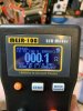
I had forgotten that I have recently gotten an ESR meter. Duh! Please, see the attached for the reading. If I'm reading this correctly, the C3 cap is not good? Can you help me understand the reading? I'm still going to replace the capD56D5B72-2A16-4E89-8FBE-75FD8E902744.jpeg 4A5478B1-79CB-4C27-8618-AC57A39C92CE.jpeg but wanted to better understand the measurement reading.
 
Measure the ESR of the new one before you install it (if its not too late).
Caps block DC, so the impedance (like resistance) has to be measured with an ac signal. The ESR meter uses an ac signal and calculates the Equivalent Series Resistance that is comparable to a resistor to evaluate the losses that may occur in the cap. A perfect cap would have an ESR of 0Ω. So 0.1Ω is good (I guess). I have read so many 'explanations' of ESR and its value relationships it makes my head spin. The only thing I can figure out is that, in most applications, lower is better. Too many variables. If you have a bunch of new ones you can get a baseline for your readings. :dunno: The little chinese multi-function unit I have sometimes gives negative ESR values :thumbsdown:. Wish I had a better answer for both of us . . .
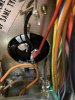
 
So, I've replaced C3 with an EPCOS 1000uf 100v cap. I checked the cap before install and all was good. The old cap gives me an OL reading. However, no change the relay is still not clicking.

Measurements:

Pins 12 & 13 26.6acv
Pin 14 +34vdc
Pin 15 -34vdc

C1 +34vdc
C2 -34vdc

Collector Q1: -1
Base Q1: -1
Base Q2: 0
Cathode D6: 0

So, I'm guessing that the Q values are even worse than before?
21D5CA52-F273-4CB9-A6E2-29083571B097.jpeg
 
Measure the ESR of the new one before you install it (if its not too late).
Caps block DC, so the impedance (like resistance) has to be measured with an ac signal. The ESR meter uses an ac signal and calculates the Equivalent Series Resistance that is comparable to a resistor to evaluate the losses that may occur in the cap. A perfect cap would have an ESR of 0Ω. So 0.1Ω is good (I guess). I have read so many 'explanations' of ESR and its value relationships it makes my head spin. The only thing I can figure out is that, in most applications, lower is better. Too many variables. If you have a bunch of new ones you can get a baseline for your readings. :dunno: The little chinese multi-function unit I have sometimes gives negative ESR values :thumbsdown:. Wish I had a better answer for both of us . . .
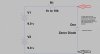
I did measure the ESR prior to installing and had the same values? User error?
 
I'm also curious as to why the relay did click on a few days ago, after taking measurements it just clicked and was working. Shut down the unit and back to square one. Quite frustrating. Is it possible that the relay is just shot?
 
Until you have +36vdc from pin 7 of the power supply the relay cannot pull in. It now looks like both 0.5A fuses are blown, or both rectifier diodes (in D5 dual diode) since there is no positive voltage on the collector of Q1 at all. With the black lead on ground measure ac volts on each side of both fuse holders for FU3 and FU4, also pin 9 & pin 10. Measure dc volts on the + side of C3 (1000µF).
On a dc volts range OL means a higher voltage present than the range can resolve, step up the meter one range. What are you measuring that cap (setting and range, or is that an esr reading?) You measured +46vdc on pin 8 once before, I think.
The relay click puzzles me also, did you check continuity for the traces to pin 8 from Q1, also pin 9, pin 10 and D5? Reflow the solder on that pin.

Check continuity to ground for pins 1 and 11.

EDIT: more
 
Until you have +36vdc from pin 7 of the power supply the relay cannot pull in. It now looks like both 0.5A fuses are blown, or both rectifier diodes (in D5 dual diode) since there is no positive voltage on the collector of Q1 at all. With the black lead on ground measure ac volts on each side of both fuse holders for FU3 and FU4, also pin 9 & pin 10. Measure dc volts on the + side of C3 (1000µF).
On a dc volts range OL means a higher voltage present than the range can resolve, step up the meter one range. What are you measuring that cap (setting and range, or is that an esr reading?) You measured +46vdc on pin 8 once before, I think.
The relay click puzzles me also, did you check continuity for the traces to pin 8 from Q1, also pin 9, pin 10 and D5? Reflow the solder on that pin.

Check continuity to ground for pins 1 and 11.

EDIT: more


Evening, the two 0.5A fuses were blown, you know your stuff. I know right, the mystery of the relay click. I've looked over the traces, to my eyes, everything looks good. But did see several solders that I thought should be reflowed. I've also have done this for pins 8-11 as directed. I use my DMM to measure the cap. I did the following measurements.

FU3: 36.8/36.8acv
FU4: 36.8/36.8acv

Pin 9: 36.8acv
Pin 10: 36.8acv

C3 46dcv

Pin 12: 28vdc
Pin 13: 26vdc
Pin 14: 32vdc
Pin 15:-32vdc

C1 32
C2 32

Q1 C: 44vdc
Q1 B: 18vdc
Q2 B: 7vdc

D6 C: 6vdc

Pin 7: 18vdc
Pin 8: 46vdc

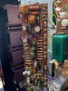
These measurements are near or above the first set of measurements that you had me take. So, hopefully, that is some progress. I started thinking about Pin 7 needing to be at 36vdc to hear the lovely sound of the relay click. Since pin 7 is half of what it should be, I followed pin 7 wirings to pin 16 on the protection board. Pin leads to R16. It's an ugly green resistor that looks a bit fuzzy. Not quite sure what to make of it. It just doesn't look right. I don't recall seeing one like this and couldn't find another one in the receiver on the boards that I have pulled at the time. Anyway, I pulled one end of R16 from AWM-011 and it measured 0L. I'm on the assumption that this is a bad resistor and is part of the problem? Here it is...let me know what you think. Thanks!

9872050F-C4F0-4484-AD6C-AB3A8D462CC6.jpeg
 
Evening, the two 0.5A fuses were blown, you know your stuff. I know right, the mystery of the relay click. I've looked over the traces, to my eyes, everything looks good. But did see several solders that I thought should be reflowed. I've also have done this for pins 8-11 as directed. I use my DMM to measure the cap. I did the following measurements.

FU3: 36.8/36.8acv
FU4: 36.8/36.8acv

Pin 9: 36.8acv
Pin 10: 36.8acv

C3 46dcv

Pin 12: 28vdc
Pin 13: 26vdc
Pin 14: 32vdc
Pin 15:-32vdc

C1 32
C2 32

Q1 C: 44vdc
Q1 B: 18vdc
Q2 B: 7vdc

D6 C: 6vdc

Pin 7: 18vdc
Pin 8: 46vdc

These measurements are near or above the first set of measurements that you had me take. So, hopefully, that is some progress. I started thinking about Pin 7 needing to be at 36vdc to hear the lovely sound of the relay click. Since pin 7 is half of what it should be, I followed pin 7 wirings to pin 16 on the protection board. Pin leads to R16. It's an ugly green resistor that looks a bit fuzzy. Not quite sure what to make of it. It just doesn't look right. I don't recall seeing one like this and couldn't find another one in the receiver on the boards that I have pulled at the time. Anyway, I pulled one end of R16 from AWM-011 and it measured 0L. I'm on the assumption that this is a bad resistor and is part of the problem? Here it is...let me know what you think. Thanks!

View attachment 2026625

Edit: I pulled R19 (.47 2 watts) NOT R16.
 
What board is in the picture with the green resistor? Can you post a picture of the whole board, Please? What version of the protection board do you have? The SX-727 had multiple versions, and they are very different in small details. Label is like AWM-nnn followed by a letter.
Check traces for continuity with your meter, sometimes cracked traces are not visible.
That green resistor is a wirewound one, it should measure a very low resistance, 0.47Ω. Put your meter on its lowest ohms range and touch the probes together. That will be your meter lead resistance, write it down. Now measure across that resistor, what does it read? Subtract the lead resistance from the measurement to get the actual resistance.

Unless the Protection board is loading down the power supply regulator it is not causing the low voltage. Does does power supply Q1 get hot?
 
Last edited:
D6 should not be +6vdc, it should be +13vdc. Verify you are not putting a 6v zener in where a 13v belongs. We have to get the regulator working before worrying about the protection board internal circuit downstream from the power supply.

Zener test jig:

ZenerTest3.jpg
 
What board is in the picture with the green resistor? Can you post a picture of the whole board, Please? What version of the protection board do you have? The SX-727 had multiple versions, and they are very different in small details. Label is like AWM-nnn followed by a letter.
Check traces for continuity with your meter, sometimes cracked traces are not visible.
That green resistor is a wirewound one, it should measure a very low resistance, 0.47Ω. Put your meter on its lowest ohms range and touch the probes together. That will be your meter lead resistance, write it down. Now measure across that resistor, what does it read? Subtract the lead resistance from the measurement to get the actual resistance.

Unless the Protection board is loading down the power supply regulator it is not causing the low voltage. Does does power supply Q1 get hot?

The board in the picture is the protection board (AWM-011). See attached picture. I'll check the traces for continuity with my meter. (I've not done this before, but I'll see what I can figure out.) When I measured R19 on AWM-011 it measured OL, on ohms, kOhms, M Ohms....I did get a new meter today and will hopefully, be trying it out later tonight and will plan to remeasure the resistor.

I'll check the power supply and whether Q1 is getting hot. I want to say that it has been but can't say for sure.

716715CB-80B7-41EB-B4A3-4F1E9B6A5D5C.jpeg 67843A6A-3834-4850-B415-9CDA39EEFB25.jpeg 6DD84250-8F75-4516-9263-4032AB8CD7E4.jpeg
 
Thanks for the pictures!
Looks like there is an added diode across pins 14 and 15, remove it for now, please.
It also appears not to have been rebuilt with new transistors and caps, except maybe Q7 (the relay driver).
BUT the power supply has to be fixed first, or there is no way to tell if the Protection pcb is working or not.
What about the zener D6? Is it a 6v or 13v zener?
 
Thanks for the pictures!
Looks like there is an added diode across pins 14 and 15, remove it for now, please.
It also appears not to have been rebuilt with new transistors and caps, except maybe Q7 (the relay driver).
BUT the power supply has to be fixed first, or there is no way to tell if the Protection pcb is working or not.
What about the zener D6? Is it a 6v or 13v zener?

Hello, I've removed the diode across pins 14 & 15. The board was rebuilt with new transistors (not all as the pictures show) and Nichicon PW caps. I've measured the zener and it looks like its a 6v. I'm not sure why this isn't the correct 13v zener. I had purchased 3 kits (PSU, Protection, and Phono boards) a few months back for the 727 of the web. I'm wondering if I've installed the 13v zener in a different location. I'll check on that as well. Otherwise, I'm going to have to order or see if I can find a local electronics store that may have them. I, of course, placed an order with Mouser earlier this week for caps, etc. for a turntable that I'm planning to refurbish. Can you recommend or know what the specific part number would be for the correct Zener (I will also look, I don't expect you to hold my hand every step of the way. :) ) ? I'm studying for a real estate exam that I'm taking on Monday, so I haven't had the chance to check the continuity of the board traces, hopefully later tonight or tomorrow. Thanks again for all of your help.
 
Back
Top Bottom