• The move to the new server is done. There are some software and database maintenance updates in process. This has us passing the hat around to help out. We appreciate any donations. Seriously, even a dollar helps. The payment page may be found here - https://www.audiokarma.org/support.html

Pioneer SX 737 Rebuild with pictures

rkeller

Member
Had tons of fun restoring an SX-780 and two 636s (one for my son and another for my daughter, who’s starting to spin vinyl). My friends and family had either forgotten or never knew, just how good music can sound. I was able to pick up an SX 737 from a local Salvation Army store. FYI they are figuring out what these units are worth...
 
Register to hide this ad
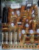
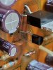
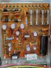
14CC09FE-51E4-4F07-866A-BA4EFCB35F55.jpeg 22BA80EB-3644-4CAC-8BAF-3DFD1F581CCE.jpeg Power supply AWR-057-0
Replaced transistors, diodes, zeners and caps then had R9, a 270ohm resistor, lose it’s smoke.
 
5891D217-7AF4-43C4-BB61-1583C5EBC1B0.jpeg First thoughts were Q1 and or 2 were shorted or in wrong but they looked OK.
Also big thank you to all those who worked to put the parts list together and keep it current.
 
AC33F4DD-A8B5-4F3C-92FD-5CEE41B5784A.jpeg 425A1E7D-85CF-40E1-9271-90B58AB4D032.jpeg Everything else topsides looks Ok. Quick voltage check:
Input to Q1 48v, output 24v. Output on 15 and 16 zero due to burnt R9.
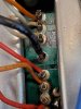
Isolation transformer not showing excessive current so I flipped her over and voila.
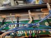
Chassis ground wire snapped off pin 18 and sat shorting the output of R9. To much flexing from all the desolder & resolder. Soldered black ground wire back to pin 18 and replaced R9.
 
0C46F0F8-C47F-4286-9A76-92FF78B10824.jpeg C64DA318-C889-4253-AF2D-B78258D498FA.jpeg 6B2AC093-E2B0-47DD-969B-3143675AFE9C.jpeg Hooked up an alligator clip to the antenna and a couple old 8 ohm car speakers and with the volume all the way down, tried the unit out for the first time.
FM, Aux and the dial pointer lights are out.
Snap, crackle, pop, rice crispy intermittent noise, which on other rebuilds came from the 2SC1451’s on the power amp board.
Nice thing is it picked up a local FM station, kind of... the tuning wasn’t centered, but the stereo light came on and the speakers, protection relay, balance, etc. all seem to be working.
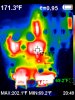
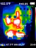
Here’s a thermal of the power supply board. Look at what a difference the heat sink makes. I think both the 2SD313’s will end up with one. 118f with 171f without.

 
Nice pictures!!
I'm glad you found the problem. Definitely a lot of stress on the wiring.
That resistor really got cooked.
Are you using a DBT? Just curious. I'm working on an SX-636 and am trying to power it up that way. So far nothing has popped, burnt or exploded.
 
Before I go any further do you have a specific order of operation that works well when going through an entire unit?
And.
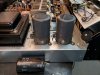
The two big electron storage units. The new electrolytic capacitors are, of course, smaller and just don’t look right in the unit. The originals test fine. Is it recommended to change those because they are electrolytics or run with the originals until there’s a problem?
Thanks tons for all the great info you all share on the site.
 
Nice pictures!!
I'm glad you found the problem. Definitely a lot of stress on the wiring.
That resistor really got cooked.
Are you using a DBT? Just curious. I'm working on an SX-636 and am trying to power it up that way. So far nothing has popped, burnt or exploded.
No dim bulb tester yet, started with a dmm then will progress to a scope when I get into the audio sections.
I’m using a Tenma Variable transformer. I like to slowly bring up the voltage and watch the current when I first start. Then again every time I finish with a section.
Congrats on the 636, that was what I was looking for when I stumbled onto the 737. Great! Sounding units and plenty powerful enough for just about any room. If you don’t already have speakers try the Pioneer SP-BS22 bookshelf speakers. For my taste a perfect pairing. Plenty of rich full sound that is loud enough for my 20+ year olds and precise enough for my picky ears. Best thing is they won’t put you in the poor house.
 
Definitely watching as I've got a 737 sitting on the shelf due to making bad noise. Just don't have time right now to play with it.
 
Well I'm basically a novice (not sure I should be giving advice :)) but have had a few successes, most noteworthy was an SX-434 - the upgrades and advice I got here really transformed it, I love how it sounds.

The new electrolytic capacitors are, of course, smaller and just don’t look right in the unit. The originals test fine. Is it recommended to change those because they are electrolytics or run with the originals until there’s a problem?
Here goes my attempt at advice on those:
  • I think it's recommended to replace.
  • I think even though you can check capacitance it's more difficult to check other characteristics (possibly leakage?).
  • Those caps are 50 years old and have exceeded their life, period.
  • Sometimes people put different values in . . . affects the sound and you might like it?
  • You might as well while you are in there!
  • You can cut open the old caps and "stuff" the new ones in there. I might do this on my SX-636 project.
  • You can search on Mouser for caps of a certain capacitance and diameter so that they are a closer fit to the clamps.
  • You can use some gasket material, maybe even electrical tape (I did it) to make it a better fit too.
I hope that helps. Will be watching your project!
 
View attachment 1713724 View attachment 1713722 View attachment 1713723 Hooked up an alligator clip to the antenna and a couple old 8 ohm car speakers and with the volume all the way down, tried the unit out for the first time.
FM, Aux and the dial pointer lights are out.
Snap, crackle, pop, rice crispy intermittent noise, which on other rebuilds came from the 2SC1451’s on the power amp board.
Nice thing is it picked up a local FM station, kind of... the tuning wasn’t centered, but the stereo light came on and the speakers, protection relay, balance, etc. all seem to be working.
Here’s a thermal of the power supply board. Look at what a difference the heat sink makes. I think both the 2SD313’s will end up with one. 118f with 171f without.
What camera did you use for the thermal picture? I like to get one for myself, but not a professional camera, just for home use only.
Still looking for some cheap China thing I can use with a notebook or a software on my android smartphone.
 
Redo the main caps as long as you're in there. Go up a bit in voltage and capacitance and you can find something that fits. Leaving the old ones in there just looks lazy, and using smaller caps and gasket material or whatever just looks bad.
 
6DB51DD4-D8CC-4834-BD75-7B898D7DD416.jpeg 0A4D66E5-8277-4EC9-89FF-9DDAEFA1FD2D.jpeg BB99E0FE-9654-4840-8467-A37EBE28E9BC.jpeg Thanks for the suggestions.
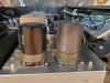
Here’s what I came up with for the mains.
Mouser part number 647-LKG1K103MKNF
Same diameter but a little taller.
The smaller KEMET is the direct replacement but silly small.
 
I ordered a replacement led for the dial pointer light from vintage audio, but it’s a couple mm too big and too white.
Has anyone found a good replacement?
 
That thermal camera looks really good, but it's fare above my budget. Have to find a cheaper one or wait for the next Black Friday.
 
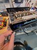
20200105_120206.jpg
removing the plastic overlay, I used a heat gun on low to soften the adhesive on the inside bottom of the overlay.
 
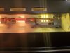
20200105_120626.jpg
The originals had a yellow orange glow, the led replacements from vintage audio are called warm white, or yellow white.
Notice how the white indicator plastic was sagging in the lights above. I could tell which functions were used the most. Some were even a little discolored. Those incandescent indicator bulbs must have gotten a little warm. They'll be changed out with LEDs also.
 
Last edited:
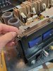
20200105_121408.jpg 20200105_121416.jpg
The meter bulbs push out fairly easily through the bottom of the metal shield which was removed by taking out the two top screws.
 
Last edited:
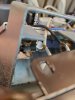
20200105_125336.jpg 20200105_125433.jpg
I used a heat gun on low to soften the indicator housings and try and pull or push the old bulbs out. Then while they were still warm I inserted the new LED's through the front, wires first through the holes and used clear GE silicone to hold them in place. I used a small screwdriver to reform and try to reshape the warped holders that had partially melted from the old bulbs.
After I was done I realized it may have been simpler to partially remove that whole assembly.
 
Back
Top Bottom