• The move to the new server is done. There are some software and database maintenance updates in process. This has us passing the hat around to help out. We appreciate any donations. Seriously, even a dollar helps. The payment page may be found here - https://www.audiokarma.org/support.html

Pioneer SX-780 Repair help

Biscayne

New Member
Hi everybody,

I am in the process of restoring a Pioneer SX-780 and would need some guidance from the gurus to get it to the finish line. The unit powers on and never blew fuses but had 1, possibly both STK's blown and protection relay would not click. This made sense as the voltages at the STK pins 1,3,8,10 were way off.(+& - 36-41V)
I have since changed almost all the caps, diodes, half a dozen out of spec resistors, and a dozen transistors with recomended replacements from this site. Now the relay clicks and comes out of protection and have the following voltages with packs out and 1k resistors soldered in, which is promising.

RIGHT LEFT
Pin 1: -3.5v Pin 1: -4.5v
Pin 2: -39v Pin 2: -39v
Pin 3: 0v Pin 3: 0.04v
Pin 8: 0.03 Pin 8: 0.04v
Pin 9: 38.8v Pin 9: 39v
Pin 0: 3.75v Pin 0: 4.68v

Q25: 13.36v, 14v, 22.6v
Q19: 38.8v, 39.5v, 47.5v

*Q20: -48.4v, -49.2v, -49.7v

Clearly a problem with Q20. I have swapped replacements for Q20(2SB536 replacement), Q24 (J113 replacement), Q22 (KSA1013YBU replacement) and nothing has changed. Im not sure if im blowing replacements as I havent found or addressed the root problem.

Here are some other failed test points I found that should help in troubleshooting the problem:

C307: +39v (good)
C308: -50v (bad)

R238 top: -50v (s/b -39.5v)
R238 bottom: -38.4v (s/b -17.1)

R237 top: -50v (s/b -39.5v)
R237 bottom: -38.4v (s/b -17.1v)

Q6 ( E: -0.57v, C: 39v, B: 0v )
Q5 ( E: -0.57v, C: 39v, B: 0v )

R240 bottom: -0.57v (sb -13.5v)
R239 bottom: -0.57v (sb -13.5v)

Please advise where to test next and what voltages to report.

Thanks!
Dave
 
Last edited:
Register to hide this ad
Clearly a problem with Q20. I have swapped replacements for Q20(2SB536 replacement), Q24 (J113 replacement), Q22 (KSA1013YBU replacement) and nothing has changed. Im not sure if im blowing replacements as I havent found or addressed the root problem.
When it comes to troubleshooting power supplies it is best to disconnect the loads because you have to first determine if it is an over load or the power supply itself. Not so easy when the unit has no ways to disconnect the load.
So you can measure the load currents indirectly by measuring voltage across series resistors such as R317,318, assuming that they are not out of spec, which you measure first with the power off.
When changing components, verifying pin out is so important, things to double check if it is not working
Q20: -48.4v, -49.2v, -49.7v
Am I supposed to guess what pin is what voltage?
Best to mark up a schematic showing all the voltages, even the ones Pioneer did not mark on the schem, around the Q20 -ve regulator. It gets referenced to the +ve regulator which is working correctly, so it is only a couple of components and it is probably not Q20, which you can easilly check with your DMM in diode mode (power off again, circuits discharged) for the junctions being intact.

Where the hell is the troubleshooting guide on this web site?
 
Greetings, and Welcome to Audiokarma!
Power supplies first. Black lead clip to chassis/ground. Unregulated supplies: measure dcv on pin 11 of main PCB, should be about +40vdc; measure dcv pin 10 of main PCB, sb -40vdc.
The negative regulated supplies depend on the positive supplies being correct first.
Since the primary positive regulator appears to be working correctly, measure dcv on the + side of C310, sb -0.6vdc. From the Q20 voltages (if replacement is installed correctly) I suspect Q22 is open. Replace Q22 with 512-KSA992FBU (Mouser #) and, at the same time replace Q20 with 512-KSA940TU. Don't power up between replacements of those two, They tend to take each other out in a circular failure when replaced one at a time. Then recheck vdc on emitter of Q20.
Note: Q19, Q20, and Q25 (especially) tend to unsolder themselves from heat over time, and can benefit from better heatsinking. Reflow the solder on those if you have not already.
 
Thanks! This is my 2nd SX-780 that i am helping a friend repair. I easily repaired my 1st reading all the SX-780 posts on this site, which was a pretty straight forward STK pack replacement.

R317 &R318 were both replaced, 2.2ohm still in spec. R317 has 49.6v on both sides, R318 has -51.7v on both sides.

Pin 11: 39.7v
Pin 10: -39.5v

C315: - side: -51.2v, +side: 0v

C310: - side: -50v, +side: -6.15v

Q19, Q25, Q20 have all been resoldered. Unfortunately 2 pads on Q20 are damaged and lifted from the PCB. I had to solder two small jumper wires to connect them to their respective traces.

I had replaced Q22 with KSA1013YBU, but have 4 KSA992FBU onhand if that is better suited. I only have one KSA940TU onhand for Q20.
Based on the voltages posted above is it safe yet to replace Q22 & Q20? I dont want to blow my only KSA940TU, Mouser delivery to Canada is slow!
 
Welcome Aboiard!

Mind you, it's only one opinion, but Q19/Q20 are probably up to the task in their original configuration. Q25 is most frequently the trouble-child of the regulators. All of them can get hot, and need to dissipate that heat. The failing of the original design is that there's just not quite enough heat sink to get it done properly. If the transistors are still functioning, you may want to consider retaining them and simply adding heat sink area. Be aware that the heat sinks are energized, so isolation is necessary.

For the Q22 position, a KSA992 is an approximate equivalent. A KSA916Y is a bit more robust, and is not on (yet) the short list for obsolescence. The KSA1013 you installed there should be a good selection.

For Q20, the KSB596Y could be a good replacement if you don't want to sacrifice your last KSA940.
 
Last edited:
Thanks! This is my 2nd SX-780 that i am helping a friend repair. I easily repaired my 1st reading all the SX-780 posts on this site, which was a pretty straight forward STK pack replacement.

R317 &R318 were both replaced, 2.2ohm still in spec. R317 has 49.6v on both sides, R318 has -51.7v on both sides.

Pin 11: 39.7v
Pin 10: -39.5v

C315: - side: -51.2v, +side: 0v

C310: - side: -50v, +side: -6.15v

Q19, Q25, Q20 have all been resoldered. Unfortunately 2 pads on Q20 are damaged and lifted from the PCB. I had to solder two small jumper wires to connect them to their respective traces.

I had replaced Q22 with KSA1013YBU, but have 4 KSA992FBU onhand if that is better suited. I only have one KSA940TU onhand for Q20.
Based on the voltages posted above is it safe yet to replace Q22 & Q20? I dont want to blow my only KSA940TU, Mouser delivery to Canada is slow!

I find Didgikey delivery way quicker and cheaper to Alberta, I do use both vendors as one seems to be out of something in an order I need inevitably.
 
I had replaced Q22 with KSA1013YBU, but have 4 KSA992FBU onhand if that is better suited. I only have one KSA940TU onhand for Q20.
Based on the voltages posted above is it safe yet to replace Q22 & Q20? I dont want to blow my only KSA940TU,
Looks to me like Q22 is open BE, or installed incorrectly. If you have multiple replacements for Q22, but only one for Q20, I would break my usual rule and replace just Q22 to start with. If that solves the regulator issue you can replace Q20 or not, now or later (after getting more KSA940s). If it does not fix it, and Q20 is blown (and it pops Q22 again) you have only wasted one KSA992FBU transistor. Then replace both at the same time. Note that the 6-way transistor test on the meter's diode range can prove a transistor is bad, but passing the test does not prove it is good.

The KSA1013YBU is a higher current (Ic) than the KSA992FBU, but is is lower gain and lower fT. The gain and speed are more important in that location, as it is the negative feedback through R311, C310, and the base of Q22 that controls the voltage regulation. I would use the KSA992FBU.
 
Last edited:
I installed a TO220 mica and bolt insulator when i changed Q20. Now the heat sink is not live. Is that correct, should i do the same to Q19, Q25 as well? When using mica insulators do i still use thermal grease?

I will try Digikey for sure on my next order. My Mouser order took 3 weeks to arrive, mind you it was during holiday season in December + COVID. They did reimburse my shipping.

I dont have any KSB596Y. I do have some TIP30C and TIP32C and a NTE292. Are any of those suitable for Q20? (I know everybody frowns upon anything NTE on this site!)
I can also still source locally some NEC brand 2SB536 from an electronics store. They must be old, safe to use or stick with modern KSA940TU?

I will swap KSA1013 for a KSA992. If that doesnt work I will change both Q22 & Q20 and install my last KSA940.

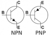
* Q22 orientation - can i trust the printed E on the PCB to indicate the emitter legs? What does the arrow indicate? To confirm Q22 the emiter is the 3rd hole furthest away from the face of the unit correct?
 
Since there is only one component attached to the heatsink on Q19, Q20 and Q25 they do not NEED to be isolated. The risk is touching the 'sink and shorting it to another component during trouble shooting. Thermal grease is always used with mica insulators.
The Arrow is always the emitter, no matter how the drawing is oriented. I have not seen or heard of any label errors on the SX-780

transistor_images.png

You can check the emitter label is correct by testing resistance to ground (power off), it should be 0Ω
Verify C310 is installed correctly and is not shorted or leaky.
The emitter of Q20 is more negative than the base or collector? That cannot be correct, recheck which legs you are measuring.
What is the vdc of base of Q22 now?
 
Last edited:
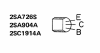
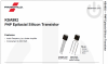
The Q22 original 2SA904A and the replacement KSA992 have different leg orders that you have to be aware of when you install it.
The KSA992 will 'face' the other direction from the 2SA904A.
Recheck your orientation of Q22.


2SA904crop.png KSA992crop.png
 
Last edited:
C310 is new and installed correctly. I pulled it and double checked capacitance 2.2uf and ESR is 3 ohm.

You are right about Q22 KSA992. Last night i thought the same and tried flipping it to the correct orientation but it instantly burned with a puff of smoked when I powered it on. No fuses blew, unit was on for 1-2 secs. That confused me into thinking it was incorrect so I installed new one (backwards) BCE vs correct ECB. I assumed it was correct as it didnt smoke and relay clicks in that orientation.

I just discovered Q24 (2SK34 - DGS) was replaced in the same orientation with J113 (DSG) which is incorrect. Would this cause Q22 to smoke when installed correctly or am i just compounding problems on top of a problem?

I will now double check all the new transistors I installed for similar errors. Rookie mistake!
 
C310 is new and installed correctly. I pulled it and double checked capacitance 2.2uf and ESR is 3 ohm.

You are right about Q22 KSA992. Last night i thought the same and tried flipping it to the correct orientation but it instantly burned with a puff of smoked when I powered it on. No fuses blew, unit was on for 1-2 secs. That confused me into thinking it was incorrect so I installed new one (backwards) BCE vs correct ECB. I assumed it was correct as it didnt smoke and relay clicks in that orientation.

I just discovered Q24 (2SK34 - DGS) was replaced in the same orientation with J113 (DSG) which is incorrect. Would this cause Q22 to smoke when installed correctly or am i just compounding problems on top of a problem?

I will now double check all the new transistors I installed for similar errors. Rookie mistake!
Yes, the FET is connected as a constant current source (limiter). If installed wrong it can/will let max current flow from the power source, frying the FET and Q22. :oops: It might damage R318 (2.2Ω) in the process. R318's job is to be a very slow blow fuse, so the amp does not go up in flames.
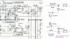
 
R318 doesnt seem to be damaged, 2.3 Ω
I will start over and install a new J113, KSA992 and TIP32C with correct pin orientation!
Thank you so much for your help and guidance.
 
You are most welcome!
Sadly, now you see how they can easily damage each other when improperly installed.
 
Last night i found Q28, Q29 (2SK34) had the same problem with J113 replacements. I swapped in 2 new J113 with correct DGS pinout. All other replacement transistors were correct.

New Q20, Q24, Q22 installed. This time nothing smoked with correct DGS pinout on Q24. Unfortunately it didnt change much.

Q20, B: -50.4v, C: -51.5v, E: -51.2v

Q24: D: -51.4v, G: -51.7v, S: -51.7v

Q22: B: -51.4v, C: -51.4, E: 0v

It did balance out left and right STK pins 1 & 10 compared to the voltages initally posted.

RIGHT
Pin 1: 5.4v
Pin 2: -40v
Pin 3: 0.17v
Pin 8: 0.17v
Pin 9: 40v
Pin 0: -5.80v

LEFT
Pin 1: -5.40v
Pin 2: -40v
Pin 3: 0.16v
Pin 8: 0.16v
Pin 9: 40v
Pin 0: 5.80v
 
You can do a quick test of that regulator by replacing the jfet with a resistor. You know the voltage drop across it so calculate the value based on 2mA of current to flow
 
Back
Top Bottom