• The move to the new server is done. There are some software and database maintenance updates in process. This has us passing the hat around to help out. We appreciate any donations. Seriously, even a dollar helps. The payment page may be found here - https://www.audiokarma.org/support.html

Pioneer SX-780 Voltage Regulator Trouble

CaseyWKC

Active Member
Hey all, I have an SX-780 that refuses to come out of protect. PA3001 isn't getting the 13.5 volts it needs to come out of protect, but there are more issues.

Q25 - 2SD712
7.6v on emitter
7.2v on base
8v on collector

Q13 - 2SD325R
25v on emitter
28v on base
25v on emitter

C316 has the 51.7v it should have on positive

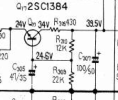
Q17 2SC1384 reads :
15v on emitter instead of 24v
20v on base instead of 24.6v
15v on collector instead of 34v

I've recapped most of the protection board and replaced 2SD712.

Both 2SK34's seem to be working as they should too.

Any help would be greatly appreciated.
 
Register to hide this ad
Check R305. If it's ok, something is drawing too much current out of Q17.
View attachment 3601521
Yupp, the resistors check out at 430 ohms.

I will go check voltages around Q17, but I've already replaced those 100uF caps, and 47uF caps, along with checking all of those resistors.

The only thing I haven't done is replace Q17.

I can trace the 7 volts back before Q17 if that's of any help.
 
Yupp, the resistors check out at 430 ohms.

I will go check voltages around Q17, but I've already replaced those 100uF caps, and 47uF caps, along with checking all of those resistors.

The only thing I haven't done is replace Q17.

I can trace the 7 volts back before Q17 if that's of any help.
Just as a sanity check, measure the voltage on both ends of R305.
 
One side measures 19.53v - other side is 25.3v
Well you only had like 7V on Q17 so you either have a broken trace, bad solder joint (it is Pioneer, after all) or measurement error. Look for a circular crack in the solder joints on Q17.
 
Well you only had like 7V on Q17 so you either have a broken trace, bad solder joint (it is Pioneer, after all) or measurement error. Look for a circular crack in the solder joints on Q17.
The input side of R305 should have 39 volts on it. You are 9 volts in the hole before you even get to Q17.
Confirm the 39.5 volts is present. If it is off then the rest of circuit after it will be off as well.

If the 39.5 supply is low go back to Q19 and look at those voltages.

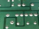
As @dr*audio said look at the solder joints on the three transistors that are heatsinked. They ALWAYS develop problems as they run very hot.
After you look at them just go ahead and reheat all of them and perhaps add a touch of fresh solder.


780ps1.jpg
 
Last edited:
The input side of R305 should have 39 volts on it. You are 9 volts in the hole before you even get to Q17.
Confirm the 39.5 volts is present. If is is off then the rest of circuit after it will be off as well.

If the 39.5 supply is low go back to Q19 and look at those voltages.

As @dr*audio said look at the solder joints on the three transistors that are heatsinked. They ALWAYS develop problems as they run very hot.
After you look at them just go ahead and reheat all of them and perhaps add a touch of fresh solder.


View attachment 3601875


Haha I assure you the first thing I did was look over every joint and reflow them.

I will do as you advised when I get home this evening. I have the whole weekend to tear into things. Thank you!
 
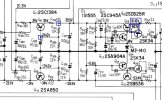
merlynski posted this about the SX-780 that I saved regarding the regulators. After reading this about Q19, Q20, & Q25 I've always refreshed solder on those whether they look bad or not.
One unit came in not working and the first thing I did was refresh the solder on them and it then worked.

Screenshot (232).png
 
I've triple checked all solder joints and reflowed ones that looked unnecessary as well just to be sure.

I went back to Q17 and and Q18 to check their voltages

Q17 - 2SC1384
E 14.4
C 18.8
B 15

Q18 - 2SA850
E -14
C -19
B -15
 
I've triple checked all solder joints and reflowed ones that looked unnecessary as well just to be sure.

I went back to Q17 and and Q18 to check their voltages

Q17 - 2SC1384
E 14.4
C 18.8
B 15

Q18 - 2SA850
E -14
C -19
B -15
Those transistor voltages look like the they are OK but the input collector voltages are low by nearly 50%. Go back to this post and have a look at the voltages at Q19 & 20.

 
Last edited:
Those transistor voltages look like the they are OK but the input collector voltages are low by nearly 50%. Go back to this post and have a look at the voltages at Q19 & 20.

Yes, I am not getting the 40 volts at the base of Q19 or Q20 I believe. (Sorry about to rush to dentist).

Q19/2SD325R
B 24v
C 47v
E 25v

Q20/2SB536A
B -24v
C -50v
E -25v

Thank you!
 
Check the voltage at the emitter of Q21. Should be 14 volts.

The collector voltages on Q19 & 20 are touch low, are you on a dim bulb? Either way nothing to get terribly concerned about.
 
Check the voltage at the emitter of Q21. Should be 14 volts.

The collector voltages on Q19 & 20 are touch low, are you on a dim bulb? Either way nothing to get terribly concerned about.
Yes I have been on a DBT just to be safe. Little higher without.

But yeah, I'm kinda stumped on this guy. I promise ya'll it isn't a cold joint. I've looked and looked, then looked some more and even reflowed the majority of joints while tracing along through the schem.
 
Yes I have been on a DBT just to be safe. Little higher without.

But yeah, I'm kinda stumped on this guy. I promise ya'll it isn't a cold joint. I've looked and looked, then looked some more and even reflowed the majority of joints while tracing along through the schem.
What about the emitter voltage of Q21?
 
Did you replace D4? Even with low voltage out of the emitter of Q19 (25V) that zener diode on the emitter of Q21 should be sitting at 14 volts.
 
Back
Top Bottom