
Not just according to the silk screen on the board, but according to the schematic?Double checked all orientation of caps and they are correct.


Not just according to the silk screen on the board, but according to the schematic?Double checked all orientation of caps and they are correct.

Pulling Q25 allowed D4 to come back to +14 and brought back the + and - 39With Q25 pulled I get the following
Q19 2SD325R
B 40v
C 52.4v
E 40.3v
Q20 2SB536A
B -40.7v
C -52v
E -40v
I measure 53.5 v across the 5W 220ohm ceramic resistor mounted to the heatsink.
Measurements from where Q25 was pulled
B 14.26v
C 53.5v
E -.027v
I did not get relay before, no lights other than the 3 bulbs illuminating the dial meter.

Emitter pad of Q25 to ground measures 1.9 MOhmsPulling Q25 allowed D4 to come back to +14 and brought back the + and - 39
Did you check the the + and - 20 something volts at Q17 & 18? I bet they are OK now.
That leaves us with why is Q25 pulling down that reference voltage?
For fun ohm check the Q25 emitter pad to ground.
Yessir I double checked the schematic and pictures I took before pulling the electrolytics to confirm orientation.Not just according to the silk screen on the board, but according to the schematic?

Emitter pad of Q25 to ground measures 1.9 MOhms
Yes you are also correct, q17 and q18 now measure the following with q25 pulled.
Q17
E 24.9v
C 33.4v
B 25.5v
Q18
E -24.4v
C -33.15v
B -24.5v
Q22 remains unchanged
Q22 - 2SA904A replaced by KSA992 :
E 0V
C -24.9v
B -.598v
with 2sd721 reinstalled in place of mje15032g readings are the same.Well there goes that theory. I thought the emitter pad might show a low ohm value, which in turn was pullling a bunch of base current on Q25 pulling the reference voltage down.
I know you replaced Q25, do you have the old one you took out? If so put it back in and see what happens to the voltages.
Something in that +13 volt circuit is dragging the zener reference voltage down. We have proved the other power supply voltages are normal without Q25 connected.
What in the world is pulling it down.with 2sd721 reinstalled in place of mje15032g readings are the same.
8v on emitter
7.9v on base
8.2v on collector
Little higher than before because I'm off dbt I'm sure.
the drop across that resistor is 41.8vWhat in the world is pulling it down.
Measure the voltage drop across that 220 ohm 5 watt resistor. That will allow us to calculate the current draw.
I= V/R
Yes in round numbers that is 190 mA. The input voltage for that circuit at the 220 ohm resistor is +51.7. we are dropping 41.8 of that across the resistor leaving only about 10 volts at the collector of Q25. So no way we get 13 volts on the emitter side. BTW at that voltage drop the resistor is dissipating 7.6 Watts.the drop across that resistor is 41.8v
I am new to actually utilizing these formulas. So 41.8/220 ohms = .19?
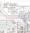
Heck yeah, now we're getting somewhere.Yes in round numbers that is 190 mA. The input voltage for that circuit at the 220 ohm resistor is +51.7. we are dropping 41.8 of that across the resistor leaving only about 10 volts at the collector of Q25. So no way we get 13 volts on the emitter side. BTW at that voltage drop the resistor is dissipating 7.6 Watts.
To hit the numbers on the schematic we will need to drop 25.8 volts across the resistor. That drop comes from drawing 117mA. So we have a larger than normal current draw somewhere on the 13.5 volt line.
Another BTW when we drop 25.8 volts across that resistor the dissipation drop to 3 watts.
Nest step is to figure out where the excess current is being drawn.
Lets start at the easier one.
Lift one end of this jumper it will remove power from the tuner circuit and a few lights and the muting circuit, they all run on that 13.5 volts.
It will leave only the protection IC on the 13.5 volt line.
View attachment 3607704

Heck yeah, now we're getting somewhere.
Jumper lifted - powered on and the relay pulled in.
2SD721 now measuring at
B 13v
C 50v
C 14v
I have 24mv of offset in the L channel and 13mv of offset in the R channel.

The drop now measures 1.68v across the 220ohm
OK The problem is not in the protection IC.
Check the other four + and - voltages and see what you have.
What is the drop across the 220 ohm. Want to see where the current draw value went.
The drop now measures 1.68v across the 220ohm
Q19
B 41v
C 51v
E 40v
Q20
B -40.7v
C -51v
E -40v
Q17
E 24.9v
C 33.5v
B 25.6v
Q18
E -24.5v
C -33.2v
B -25v

That was going to be the next test. Wet finger on the IC's of the tuner circuit.There isn't much in the tuner that can pull that kind of current in the event of failure, and whatever it is should be getting pretty hot.
 None of magic smoke has been released making it harder.
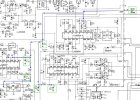
So I put the pin back and resoldered it and noticed Q6 PA1001A gets very hot very fast. Q3 - HA1197 can be ruled out as I had followed this problem there to the beginning but thought it couldn't possible be in the tuner section. Haha.I was serious about the wet finger test.
Check and see if any of the three IC's are hot.
Next check any of the e-caps in the green boxes for heat.
Whatever it is, it is not a dead short, which honestly would probably be easier to find.
It seems to be something behind a resistor or something acting as a resistor under voltage.
View attachment 3607861
Go ahead and remove Q6, they don't normally run hot. That should bring things back to working except for FM.So I put the pin back and resoldered it and noticed Q6 PA1001A gets very hot very fast. Q3 - HA1197 can be ruled out as I had followed this problem there to the beginning but thought it couldn't possible be in the tuner section. Haha.
None of the caps in the tuner section have been replaced. I will replace the caps and then if no change pull the aforementioned jumper to determine tape switch and am radio functionality.
And yes I agree, I would have very much preferred a dead short here lol.
On the bright side - if it is PA1001A, I think I have a 650 or 550 for parts around here that has one I can snag!