• The move to the new server is done. There are some software and database maintenance updates in process. This has us passing the hat around to help out. We appreciate any donations. Seriously, even a dollar helps. The payment page may be found here - https://www.audiokarma.org/support.html

Pioneer SX-780 VU Meter Issue

jdr76

New Member
Hi Team,

I have a Pioneer SX-780 that I've recently repaired. I replaced the Darlington Power Pack on the left channel which was previously shorted. After the R&R all seemed to be working correctly. Everything sounded great. In the process of testing out the unit I've been trying different speaker pairs with no issues until I recently tried a pair of brand new Kicker outdoor speakers. To my surprise with the Kickers connected the left VU meter would immediately jump to the midway point at power on and stay there even with no audio input. The Kickers are spec'd at 8 ohm impedance and 6.8 DC resistance which I believe is the sweet spot for VU meter operation.
I've tried other speaker pairs with lower impedance and the meter seems to work fine. Any suggestions?
Thanks in advance for the help.
 
Register to hide this ad
I would suspect a problem with the crossover in the speaker(s). If you have a plain 6-20Ω resistor to connect in place of a speaker, you could verify that, but it seems you've already done so with other speakers.
 
So when this happened I swapped the speakers left to right and the issue stayed on the left channel and didn't follow the speaker so don't think it's an issue with the crossover. With the new Darlington Power Pack installed does there need to be any kind of calibration performed like a DC offset adjustment. Or could there possibly be another issue at play.
 
Power on with no speakers connected and look at the meter. A dc offset will make the meters deflect. Measure dcv at the speaker terminals with a DMM and see what it is. DC offset is adjustable on the SX-780, if it is small.
 
I got a new power pack off of eBay. Probably a cheap knock off. And with no speakers connected there is zero deflection. Should I still measure dc offset?
 
I got a new power pack off of eBay. Probably a cheap knock off. And with no speakers connected there is zero deflection. Should I still measure dc offset?
I would, just to be sure. If it is offset or unadjustable the power pack may have a problem.
 
Found the time to dig into this a little deeper. I measured the DC offset on both sides. Left 0.114vdc, Right 0.083vdc. I adjusted both down close to 0. I reconnected the Kickers and tried again. Instead of tripping the left side meter immediately I can turn the volume up a little bit before it pops the left needle to center. With a different set of speakers hooked up and with no speakers connected there was no issue with the meter.
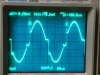
I decided to break out the scope and look at what's going on with the left channel. While running a 1kHz signal into the Aux channel and with a different set of speakers hooked up I could see on the left side that there is a little glitch on the sinewave at the zero transition points. But with a Kicker speaker hooked up to the left side the little glitch turns into a rather large ring. Turn it up much past 0.3Vpp and the output freaks out. I assume both plus and minus darlingtons turn on. I'll start working my way back up the signal chain and see what's causing it.
 
Yep, I've seen the thread. But wasn't looking to spend that much on something I was planning on selling.
Been tracing back the signal and it seems to originate before the power packs, but not a 100% sure. Suppose it could also be a feedback issue created by power packs. The 2SA979s aren't too expensive to replace, just would take awhile to get them from China.
 
Yep, I've seen the thread. But wasn't looking to spend that much on something I was planning on selling.
Been tracing back the signal and it seems to originate before the power packs, but not a 100% sure. Suppose it could also be a feedback issue created by power packs. The 2SA979s aren't too expensive to replace, just would take awhile to get them from China.
If you see it anywhere in the power amp feedback loop you will see it everywhere in the feedback loop.
You can use a pair of matched 512-KSA992FBU from Mouser for the 2SA797, and not risk possible counterfeit part purchases.
 
Good to know on the 2SA797s. My other thought is could some of the caps be going bad and causing the issue.
 
Good to know on the 2SA797s. My other thought is could some of the caps be going bad and causing the issue.
I don't think that a cap would directly cause crossover distortion, it usually is caused by insufficient bias (idle current) in the output transistors. In this case they are inside the STK, and it is not adjustable. That is likely a result of acquiring a counterfeit/fake STK. New real STK0050s have not been made for many many years, and the NOS is long depleted.
 
Ok, finally found time to swap the STK0050 from left to right and to my surprise the issue stayed on the left channel and didn't follow the new power pack. This would point back (I think?) to Q7 and Q9 which are 2SA979 and 2SA2291, respectively. I'm not 100% on how these two work in the circuit so any feedback would be welcome.
Thanks

Also attaching a pic of the 1kHz output waveform to illustrate the issue.
IMG_2223.JPG
 
WOW, that is a wild looking signal. That is not simple crossover distortion.
Is the Kicker speaker a 4Ω speaker? That may be part of the difficulty. I see quite a few here on AK say the SX-780 does not like 4Ω speakers, even though they are rated for them by Pioneer. I, personally, drove two pairs of 8Ω speakers with mine for years, in my shop, but . . . eventually I blew an STK. I suspect that a cracked bad solder job on a trace for a repair before I got it had some effect on it..

So, time for my standard SX-780 troubleshooting procedure, if you want.
Pull the left channel STK, and put a pair of 220Ω to 1kΩ resistors in its place, like this:

Pioneer SX-780 red dc-test.jpg

Actual value is not critical, but both must be the same resistance. Then measure the dc voltage at pins 0 and 1. They will (should) be close to the same voltage, but opposite polarities around 0vdc, one negative, one positive, like mirrored voltages. If you use 1kΩ resistor they will be about +/-6.5vdc, smaller resistors have lower voltages. Measure dcv at the pcb pin 9 also. Post your results, please.
 
Last edited:
As long as the colored stripes are the same you will be fine. In other words don't worry about matching them with a meter. It is just a trouble shooting process.
 
Pulled the STK and put in 400Ω resistors from 0 to 8, and 1 to 3. However, after power on I never hear the relay click. Is that an issue?
 
Back
Top Bottom