

You are using an out of date browser. It may not display this or other websites correctly.
You should upgrade or use an alternative browser.
You should upgrade or use an alternative browser.

merlynski
Curmudgeon Electronicist
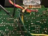
That foil pattern is definitely different than my SM. Late 1979 is towards the end of SX-780 production, as far as the info I can find.
Does (did) your unit have STK-0050 modules in it, or something else?
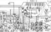
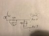
The cap between pins 9 and 0 would help prevent high freq oscillation.
The diode would keep pin 0 from forward biasing the BC junction in the STK relative to pin 9 at power up or down..
The resistor would decrease the voltage drop across Q15, maybe putting it in a more linear region of operation, and the 4.7µF cap would bypass ac around the resistor.
Does the other channel have the same change?
Can you get as good a picture from the component side?
Does (did) your unit have STK-0050 modules in it, or something else?
The cap between pins 9 and 0 would help prevent high freq oscillation.
The diode would keep pin 0 from forward biasing the BC junction in the STK relative to pin 9 at power up or down..
The resistor would decrease the voltage drop across Q15, maybe putting it in a more linear region of operation, and the 4.7µF cap would bypass ac around the resistor.
Does the other channel have the same change?
Can you get as good a picture from the component side?
Last edited:
 |
|

jdr76
New Member
I decided to deep dive this today. Started checking all the Base-Emitter voltages to see if any were out of whack. Thought Q15 was on too hard or could possibly be bad. Pulled Q15 and it checked ok but decided to swap it with Q16. No change. Then I reread your previous post about thinking that Q7 would be the next likely prospect so I swapped Q7 with Q8. No change. ACK!
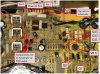
I stepped back and decided to look elsewhere. I thought maybe something else was throwing off the voltage divider of the temp resistors to the feedback circuit. I checked my soldering job to be sure it was solid. Then I spotted R263 and R265 which are 0.22 ohm 2W resistors after the STK outputs before the feedback and speaker output. I check those and sure enough R265 read open while in circuit. I pulled it out and it reads in the Meg Ohms. I used a length of test lead as a replacement and voila! Relay click. I rebiased Q5 to zero and checked Pins 0 and 1 and they are 2.7 and -2.7vdc, respectively.
Am I good to reinstall the STK0050?
I stepped back and decided to look elsewhere. I thought maybe something else was throwing off the voltage divider of the temp resistors to the feedback circuit. I checked my soldering job to be sure it was solid. Then I spotted R263 and R265 which are 0.22 ohm 2W resistors after the STK outputs before the feedback and speaker output. I check those and sure enough R265 read open while in circuit. I pulled it out and it reads in the Meg Ohms. I used a length of test lead as a replacement and voila! Relay click. I rebiased Q5 to zero and checked Pins 0 and 1 and they are 2.7 and -2.7vdc, respectively.
Am I good to reinstall the STK0050?
merlynski
Curmudgeon Electronicist
Good thinking, Good find! You do need to replace that resistor with the correct 0.22Ω one, as the bias will not be correct, and you may get distortion or blow an STK.
That is much better, and they are nicely balanced. Check that the dc offset is adjustable around 0vdc to be sure the diff amp is actually working, pull the resistors, then go for the STKs. Use a DBT for the first power up with the STK installed. You can even install one STK, then power on with DBT, if it goes dim, relay clicks and dc offset on that channel is good install the other one, repeat tests. If it passes, both channels installed, on DBT, go for full mains, recheck power supply voltages and dc offset, then try some music.
That is much better, and they are nicely balanced. Check that the dc offset is adjustable around 0vdc to be sure the diff amp is actually working, pull the resistors, then go for the STKs. Use a DBT for the first power up with the STK installed. You can even install one STK, then power on with DBT, if it goes dim, relay clicks and dc offset on that channel is good install the other one, repeat tests. If it passes, both channels installed, on DBT, go for full mains, recheck power supply voltages and dc offset, then try some music.
merlynski
Curmudgeon Electronicist
You are most welcome!I've been meaning to build a DBT, now I have an actual reason to. Resistors on order. I'll give a final update after there in.
Thanks for the help.
I am looking forward to it. I would like to get a couple of measurements from the 'new' components once it is operational, if you don't mind.
jdr76
New Member
Good morning! I replaced the faulty resistor, checked and reset the dc offsets for both sides and all looks and sounds good. I double checked the 1kHz sinewave with the scope and the zero transition issue looks to be fixed. Sound much better. I'd still like to recheck the Kicker speakers on it to see how they perform but need to wait on the weather to clear first to pull them down from outside. In the meantime, let me know what measurements you'd like me to take.
Thanks again JD
Thanks again JD
Epic discussion!!  . . . and wow! Those Pioneer staff and engineers were incredible! I'm awestruck by the quality, components and the design of the SX 780! Brilliant!
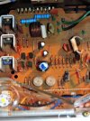
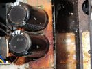
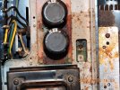
A few more photos from an "AB" (1980 February) Serial Numbered SX 780 for cross reference . . . just opened for the first time for first look to see if anything obvious is present that might indicate some work needed before attempting to power it on.
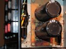
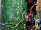
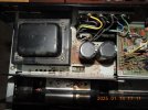
. . . also with the mysterious "GWK" Box and number 118 with an "H" identifier of some sort . . . and the second photo shows the same section as in Post #47 above . . . evidence of some repairs/mods . . . the blue resistors (0.22Ω) replaced the rectangular white resistors by the looks of it and there also appears to be some new soldering on the Q11, Q13 and Q15. The third, fourth and fifth photos show some type of dried material around the base of the filter capacitors (one in particular more than the other) and seems to be on the other side of the heat sink as well (that more or less divides the two areas). I've been speculating maybe the Filter Capacitor next to the Power Transformer spewed, or maybe someone spilled their Bloody Mary into the upper case heat grate but not much evidence of spillage haha) . . . any insights much appreciated. Haven't powered it on yet but have a Dim Bulb tester (not me! haha) ready to plug the SX 780 in through for a test after the unusual dried material is figured out a bit more. . . the sixth photo shows the bottom of the machine with is lower case removed and what appears to be a Darlington Power Pack replacement and just to the left of wire-winding "5" the array of 9 resolder pins can be seen for Q11, Q13 and Q15 along with what looks like some scratches to either ensure separation of the solder or where the solder tip was sliding to heat the solder points to accept the solder.
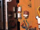
. . . and wow! Those Pioneer staff and engineers were incredible! I'm awestruck by the quality, components and the design of the SX 780! Brilliant!A few more photos from an "AB" (1980 February) Serial Numbered SX 780 for cross reference . . . just opened for the first time for first look to see if anything obvious is present that might indicate some work needed before attempting to power it on.
. . . also with the mysterious "GWK" Box and number 118 with an "H" identifier of some sort . . . and the second photo shows the same section as in Post #47 above . . . evidence of some repairs/mods . . . the blue resistors (0.22Ω) replaced the rectangular white resistors by the looks of it and there also appears to be some new soldering on the Q11, Q13 and Q15. The third, fourth and fifth photos show some type of dried material around the base of the filter capacitors (one in particular more than the other) and seems to be on the other side of the heat sink as well (that more or less divides the two areas). I've been speculating maybe the Filter Capacitor next to the Power Transformer spewed, or maybe someone spilled their Bloody Mary into the upper case heat grate but not much evidence of spillage haha) . . . any insights much appreciated. Haven't powered it on yet but have a Dim Bulb tester (not me! haha) ready to plug the SX 780 in through for a test after the unusual dried material is figured out a bit more. . . the sixth photo shows the bottom of the machine with is lower case removed and what appears to be a Darlington Power Pack replacement and just to the left of wire-winding "5" the array of 9 resolder pins can be seen for Q11, Q13 and Q15 along with what looks like some scratches to either ensure separation of the solder or where the solder tip was sliding to heat the solder points to accept the solder.
Attachments
Last edited: