• The move to the new server is done. There are some software and database maintenance updates in process. This has us passing the hat around to help out. We appreciate any donations. Seriously, even a dollar helps. The payment page may be found here - https://www.audiokarma.org/support.html

Pioneer SX-850 DC Offset Adjustment

bwv1

Active Member
The DC offset measurements obtained from this unit do not make sense to me and I'm looking for feedback as to what I am doing wrong. The unit sounds ok; I am doing this as a sort-of health checkup.

Using the measurement procedure outlined in the service manual, I measure between 17 & 18 volts (volts, not millivolts) on both channels. Adjustment of the offset pots, VR1 & VR2, does nothing to change these readings.

The service manual is very clear about how to set & measure and was followed precisely. Test points are very clear & accessible. The multimeter is fine. I have successfully performed this test many times before on other amplifiers using this same Craftsman digital meter.

I then tried to measure directly from the speaker terminals and found approx half a DC millivolt on each channel and once again, the pots do nothing to change the readings.

Any ideas about what's going on here?
 
Register to hide this ad
Is it at all likely that the DC offset adjustment pots are not functioning? It seems unlikely to me that they would both be non-working.
 
explain how you followed the directions. include pictures because you want us to be accurate.

could you have been adjusting the OTHER channel instead of the one you are monitoring?

instead of monitoring at pins 10 and 9 while adjusting VR1, put your red dmm lead on pin 11 and your black dmm lead on a bare metal chassis ground.
then adjust VR1.

it may be that your pins 9 & 24 are not grounded.
 
Thanks, Mark. I will try your suggestion although I suspect that the trim pots are not working, possibly from internal corrosion. There was no obvious way to squirt contact cleaner into them.

Pictures forthcoming.
 
Is there an opening anywhere on the DC offset adjustment pots that would allow a squirt of DeOxit to get through?
 
To rule out bad trim pots, I checked the trim pot legs directly with the meter to ensure they were working and they seem to work fine.

DC offset measurement instructions were again followed, directly from the manual, and results were the same as before: both R & L channels measure between 17 & 19 VDC. Adjustment of the trim pots resulted in this variation in voltage. I was surprised that the pots didn't produce greater variation in voltage. When power was shut off, voltage as shown on the meter dissipated slowly.
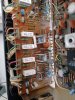
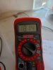
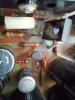
p85c.jpg p85d.jpg p85a.jpg
Next, I tried Markthefixer's suggestion of measuring between pin 11 & chassis ground. The result was the same 17 - 19 volts.

Next, I tried to measure DC at the speaker terminals and could not get a meaningful reading.

A friend suggested connecting an expendable pair of speakers and observing driver movement which could show excessive DC.
 
The DC offset measurements obtained from this unit do not make sense to me and I'm looking for feedback as to what I am doing wrong. The unit sounds ok; I am doing this as a sort-of health checkup.
Any ideas about what's going on here?
If your DC readings were correct I doubt the unit would "sound ok" or even come out of protection when turned on. You're in good hands with Mark, he's the resident Pioneer guru. Follow his future advice and don't stray to far off his instructions, good luck!
 
Some of your statements and inferences seem to be mutually contradictory.

When that happens I have to go back to the beginning and establish the actual conditions.
please take these readings, with the black lead of the dmm grounded to a bare metal (conductive!!) metal chassis ground.

AWR-101 Power Supply Voltage Measurements:
Pin 2/3 = ?v DC (+5.4vdc)
Pin 4/5 = ?v DC (+13.9vdc)
Pin 6/7 = ?v DC (+51.5vdc)
Pin 8/9/10 = ?v DC (+36.5vdc)
Pin 11 = ?v DC (+28.0vdc)
Pin 13 = ?v DC (-13.5vdc)
Pin 14 = ?v DC (-51.5vdc)
Pin 15 = ?v DC (-19.0vdc)

AWM-062 protection board
(the first 11 readings are DC voltage)
pin 1 ?v (0.000v)
pin 2 ?v (-13v)
pin 3 ?v (0.000v)
pin 4 ground
pin 5 ?v (-0.010v)
pin 6 ?v (+0.010v)
pin 7 ?v (+0.010v)
pin 8 ?v (-0.010v)
pin 9 ?v (~ +35v relay off, ~ +10v relay on)
pin 10 ?v (+36.5v)
pin 11 ?v (+36.5v)
(the last reading, pin 2 should be an AC voltage)
pin 12 ?vAC (7.5vac lamp light circuit)


Now, I am going to have to believe that when you said
"The DC offset measurements obtained from this unit do not make sense to me and I'm looking for feedback as to what I am doing wrong. The unit sounds ok; I am doing this as a sort-of health checkup."
that was referring to the past

and that you do not currently have speakers hooked up and producing sound. Voltage readings so far would have me expecting flames out of the speakers.

"Next, I tried to measure DC at the speaker terminals and could not get a meaningful reading."
As such, the protect is NOT allowing the amplifier output to be connected to the speaker terminals.
Those wires are "floating".
Thus your friend's suggestion of using some test speakers to listen to it and watch for cone movement signifying DC, is moot...

Like I said... FLAMES....


I have a suspicion YOU are going to be surprised by some of these readings.
 
Last edited:
Actual readings follow. Looks like there are some problems.

AWR-101 Power Supply Voltage Measurements:
Pin 2 = 5.4v DC (+5.4vdc)
Pin 3 = 5.4v DC (+5.4vdc)
Pin 4 = 13.9v DC (+13.9vdc)
Pin 5 = 13.9v DC (+13.9vdc)
Pin 6 = 54.8v DC (+51.5vdc)
Pin 7 = 54.3v DC (+51.5vdc)
Pin 8 = -0.9v DC (+36.5vdc)
Pin 9 = -0.9v DC (+36.5vdc)
Pin10 = -0.9v DC (+36.5vdc)
Pin 11 = 0.12v DC (+28.0vdc)
Pin 13 = -13.1v DC (-13.5vdc)
Pin 14 = -53.2v DC (-51.5vdc)
Pin 15 = -20.4v DC (-19.0vdc)

AWM-062 protection board
(the first 11 readings are DC voltage)
pin 1 17.4v (0.000v)
pin 2 -13.1v (-13v)
pin 3 17.6v (0.000v)
pin 4 gnd ground
pin 5 17.4v (-0.010v)
pin 6 17.3v (+0.010v)
pin 7 17.5v (+0.010v)
pin 8 17.6v (-0.010v)
pin 9 -0.9v (relay off) (~ +35v relay off, ~ +10v relay on)
pin 10 -0.9v (+36.5v)
pin 11 -0.9v (+36.5v)
pin 12 7.5vAC (7.5vac lamp light circuit)
 
what isn't readily apparent is that the front end of the power amp runs off the +36.5v regulated power.
that explains both amps putting out 17 to 18 volts.

of course the protect runs off the +36.5v regulated power as well.

hopefully it's just the transistor. Q5.
The missing pin 11 28v is derived from the missing +36.5v.

AWR-101: Q5 2SC1318
512-KSC2690AYS to-126 ecb 120/a160 1.2a 20w 155mhz 35-320hfe $0.40
slip on to-126 heat sink: mouser.com 532-577500B00 @0.82 ea
 
Wow, thanks for this diagnosis & prescription!
To make sure I understand correctly, on power supply board AWR-101, I should replace one 2SC1318 at location Q5 with Mouser part# 512-KSC2690AYS and it should be installed along with heat sink 532-577500B00, correct?
 
Upon reading your diagnosis many times and comparing it to the schematic, I have begun to understand at a much deeper level. I will proceed to order & install the parts and will report back here. Thanks Mark!
 
Is there enough space for the heat sink to fit? Space is pretty tight in that part of the board.
 
New KSC2690AYS was installed with no problem, being careful to observe E,C,B. I shaved the leads slightly to fit the small holes left by the 2SC1318. The first pin I measured was pin 8 on AWR101 and found 79 vDC rather than the expected 36.5. This was so far from what I was expecting that I stopped testing to await further instructions. I will also recheck whether I confused E, C or B.... It looks like the service manual shows a different orientation from the markings on the board.
 

Attachments

  • tr.jpg
    tr.jpg
    120.4 KB · Views: 21
Last edited:
further instructions: retake the awr-101 voltages (use post 10) and post them.

Be SURE the black DMM lead is connected to a BARE METAL chassis ground.
 
Looks good (once I ground things properly):

AWR-101 Power Supply Voltage Measurements post-new transistor installation:
Pin 2 = 5.3v DC (+5.4vdc)
Pin 3 = 5.3v DC (+5.4vdc)
Pin 4 = 13.9v DC (+13.9vdc)
Pin 5 = 13.9v DC (+13.9vdc)
Pin 6 = 52.6v DC (+51.5vdc)
Pin 7 = 52.6v DC (+51.5vdc)
Pin 8 = 37.6v DC (+36.5vdc)
Pin 9 = 37.6v DC (+36.5vdc)
Pin10 = 37.6v DC (+36.5vdc)
Pin 11 = 28.8v DC (+28.0vdc)
Pin 13 = -13.0v DC (-13.5vdc)
Pin 14 = -50.7v DC (-51.5vdc)
Pin 15 = -18.5v DC (-19.0vdc)
I will post AWM062 measurements next, in a minute....
 
AWM-062 protection board (post-new transistor)
(the first 11 readings are DC voltage)
pin 1 -0.1v (0.000v)
pin 2 -13.0v (-13v)
pin 3 -0.1v (0.000v)
pin 4 gnd ground
pin 5 -0.1v (-0.010v)
pin 6 -0.1v (+0.010v)
pin 7 -0.1v (+0.010v)
pin 8 -0.1v (-0.010v)
pin 9 8.9v
pin 10 37.1v (+36.5v)
pin 11 37.1v (+36.5v)
pin 12 7.7vAC (7.5vac lamp light circuit)

Looks pretty good, no?

I think the next step should be to go back to the task that brought us here in the first place, checking DC offset and idle current.
 
Last edited:
Well, inherently you already have checked (but not set) DC offset, those are the left channel pin 1(10 to 9) and right channel pin 3 (25 to 24) readings.

Easier to get to on the protect board...

also, inherently you also already read (but not set) the idle current, half at a time.
13 - (5) to 12 + (6) left channel amp board is pins 5 (-) & 6 (+) on the protect board
26 - (8) to 27 + (7) right channel amp board is pins 8 (-) & 7 (+) on the protect board

but did not include the level of precision in your report that would allow extracting the idle current data.
you just threw up the first digit of the meter's reading.
SEE, all those other digits CAN MATTER!!
 
Back
Top Bottom