• The move to the new server is done. There are some software and database maintenance updates in process. This has us passing the hat around to help out. We appreciate any donations. Seriously, even a dollar helps. The payment page may be found here - https://www.audiokarma.org/support.html

Pioneer SX-850 DC Offset Adjustment

I have learned a lot from your comments and appreciate your input greatly. Your suggestion solved the problem completely: Setting DC offset & bias as per service manual went smoothly. The 850 now works well & sounds good. The biggest personal takeaway is that my ability to read a schematic needs a lot of improvement and would never have figured this out without your input.

If it ain't broke, don't fix it comes to mind, but I have read elsewhere about making a slight modification to the AWM 062 Protect Board to:
1) Add a IN4007 diode across pins 9 & 11 to protect the transistor at Q7 from inrush current, and
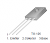
2) Proactively replacing that transistor at Q7 (2SC-138R) with a KSC2690AYS.
While the boards are already exposed, some extra KSC2690AYS are sitting nearby and the soldering iron is still warm, is this worth doing in your view?
 
yes.

do you have 0.22uF replacement capacitors? they replace the two sky blue sanyo's on the board.

pin 11 gets the banded end of the diode

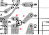
ksc2690 is e c b from left to right.
upload_2022-6-25_16-35-16.png
holes are not too small, they are clogged with old flux, push the leads through...

the c goes to the trace that connects to pin 9
the e goes to the itty bitty trace that only has 2 holes in it.
the b goes to the thick long trace .

upload_2022-6-25_16-32-43.png
 
Great, thanks.
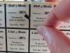
Are these old, but unused 20% Panasonic ece-a1hkr22 caps good enough to use here? They're all I have on-hand.pana.jpg
 
Once again, thank you for your guidance, Mark.

1) I notice that at shutoff, I hear a noise, kind of a cracking sound, as if some component is failing to do its job of keeping shutoff quiet.

2) And after using & testing the 850 all day yesterday, today there was a kind of loud fluttering noise at turn-on. It stopped within a second or two, but it suggests there's more work to do.

How would you suggest I proceed?
 
the AWM-062 protect board needs troubleshooting.

1. shutoff not detected and protect did not disconnect speakers soon enough

2. turn on delay too short

First, what has been changed on the AWM-062 protect board:
C1 & C2 0.22uf
Q7 ksc2690
anything else NOT original?
 
The board is otherwise original except for Q7, C1 & C2. The relay clicks on readily, after approx 3 or 4 seconds and once audible, the noise persists for approx 2 seconds. The noise sounds somewhat similar to interstation noise that might be heard when tuning between FM stations.

And this may not be related, but I noticed this too: Sometimes the tuner section, both FM and AM, craps out & will not produce sound nor do the meters register anything. I'll take a guess that I need to clean the FM & AM pushbutton switches.
 
Last edited:
the protect OFF is the (lack of) the 7.5vac lighting circuit power.

it should disconnect the amp from the outside world far quicker than any of the power supply voltages decay when turned off.
thus isolating the electronic mayhem that happens in the amp upon power down.

operate awr-101 power supply fuse FU6 (1.5 amps) like a knife switch, when open the protect should operate and de-power the relay.

Cap C5 (4.7uf 25v) is charged to about -5.1 volts by D8 and R24 / R25. Without this voltage Q6 is always on and discharging C6.
 
Does this imply that C5 and/or D8 and/or R24 & R25 may be defective and should be replaced?
 
It implies nothing. it is a guide for testing.

is the 7.5vac there? can it be switched off?

is the -5.1v there? does it disappear when the 7.5vac is switched off. and so forth....
 
1) awr-101 power supply fuse FU6 (1.5 amps) was opened and the relay opens and AWM062 pin12 goes from 7.5vAC to 0v

2) AWM062 Cap C5 (4.7uf 25v) should be charged to -5.1 volts: I measure the charge at -4.28vAC. When fuse removed it rises to 3.4vAC

3) I remeasured AWM062 pins and found very small fluctuating values at pins 1,3,5,6,7 & 8 and a small voltage at pin 4.
(the first 11 readings are DC voltage)
pin 1 +.003 to +.004v (0.000v)
pin 2 -13.1v (-13v)
pin 3 +.001 +.004mv (0.000v)
pin 4 .001v ground
pin 5 -.002 to -.005 v (-0.010v)
pin 6 +.013 v (+0.010v)
pin 7 +.013v (+0.010v)
pin 8 -.010v (-0.010v)
pin 9 8.6v on / 38v off (+35v relay off, ~ +10v relay on)
pin 10 38.4v (+36.5v)
pin 11 38.5v (+36.5v)
pin 12 7.4vAC (7.5vac lamp light circuit)
 
looks good.

do you still hear:
1) I notice that at shutoff, I hear a noise, kind of a cracking sound, as if some component is failing to do its job of keeping shutoff quiet.

2) And after using & testing the 850 all day yesterday, today there was a kind of loud fluttering noise at turn-on. It stopped within a second or two, but it suggests there's more work to do.

what is the Time delay when turned on.
this;
"awr-101 power supply fuse FU6 (1.5 amps) was opened and the relay opens and AWM062 pin12 goes from 7.5vAC to 0v"
says Q6 is ok. (replacement would be a ksc2383)
 
Relay took 4 seconds to kick-in. I did not hear the fluttering noise at startup!

There was still some noise at shutoff, but it did not seem as bad as it was previously.

Just prior to making these observations, I re-flowed all of the solder joints I made previously with the new transistor & caps on the protect board.
 
Is there a way to reduce the "thump" noise at shutoff? Turn-on is now appropriately quiet.
 
is there thump when you do this: "awr-101 power supply fuse FU6 (1.5 amps) was opened and the relay opens"

what are the conditions of the other power supply capacitors, one could be dropping even before the lack of 7.5vac (that 4.7uf cap) is sensed.


edit: I just noticed this:
I measure the charge at -4.28vAC. When fuse removed it rises to 3.4vAC

ac volts or dc volts?
 
I think that opening the FU-6 fuse was silent; I will double-check that in the morning when I have good lighting to see what I'm doing.
 
please also answer the question about power supply board capacitors. i suspect some old ones are on their last legs.
I should have been more direct - which have been replaced and which are original - that's what i meant about the word "condition".
 
Oops: I should have said about AWM062, C5: "I measure the charge at -4.28vDC. When fuse removed it rises to 3.4vDC"

And all power supply caps are original.
 
And all power supply caps are original.

There's your problem..... not all of them are still ok. they dry out, lose capacitance. most of it. less than 1 uF left...

Which is why we advocate rebuilding the power supply, protect and main amps.
Later on the phono, control and tone amps....
 
Last edited:
Back
Top Bottom