• The move to the new server is done. There are some software and database maintenance updates in process. This has us passing the hat around to help out. We appreciate any donations. Seriously, even a dollar helps. The payment page may be found here - https://www.audiokarma.org/support.html

Pioneer SX-880, FM Hum

louye2

Member
A friend recently gave me his parents' vintage SX-880 stereo receiver. It powered up nicely and I was able to play CDs through the AUX inputs and records through the PHONO inputs with fairly nice sound (slight hum). However, the FM radio has very loud humming coming from both channels. It is almost impossible to hear anything through the speakers except loud humming with some minimal music in the background.

I have attached a picture of the unit caked in dust. So far, I have only blown out the dust with a compressor and sprayed Deoxit into the various controls. I have a volt meter and good soldering skills, but not much else.

Can someone point me in the right direction on where to find root cause? I have thought about replacing those 2 giant caps next to the power supply (50V, 15000uF), but past threads on other Pioneer receivers point to a +13V regulator for the FM tuner.

Thank you for your advice.
 

Attachments

  • SX-880.jpg
    SX-880.jpg
    141 KB · Views: 41
Register to hide this ad
well, you are correct to start at the +13v since phono and aux are far less affected.

Let's see a picture of your DMM / volt meter (or tell us the make and model)

Black dmm lead to chassis ground, insulate all but the tiniest portion of the tip of the red probe. Set dmm to read at least 60 volts without overload.

Take and post DC voltage readings for pins 60 and 7 (they connect in the big white 220 ohm 5 watt off board resistor on the heat sink) on the big gwk-119 af assembly board. That will tell us a LOT.

It would be helpful if you had a cap (1 uf 250 v non-polarized) like this:
https://www.radioshack.com/collecti...radioshack-1-0uf-250v-10-metal-film-capacitor
when put in series
(red probe to one lead of the cap, the OTHER cap lead becomes your probe)
with your red test probe it blocks the dc part of a voltage reading and allows us to ferret out the AC part of a voltage reading (depending upon your meter)

If you have or get a cap like this, make AC voltage readings of pins 60 and 7 as well.

Practice finding Q26 (2sd712) - it shows in your picture. post another picture with arrow, IIAC it is the ONLY D712 marked transistor in there, and additionally, it's on it's own small aluminum free-standing heat sink.
 
Hi Mark,

Sorry for the late response. My family and I are all sick with colds, flu, or bronchitis. There is a nasty bug floating around here in NH. Attached is a picture of my volt meters and a picture of the board where pins 60 and 7 are. I noticed a lot of caked up brown liquid around the capacitors and other areas of the board. I suspect various components have just leaked due to age and that is the source of the FM humming problem. Do you agree?

I'll post the results of the voltage readings you recommended when I am feeling better. If a lot of components need to be replaced, it may be beyond my skill set to bring this receiver back to life.

Thank you for your advice.

Lou
 

Attachments

  • VOM.jpg
    VOM.jpg
    75 KB · Views: 34
  • SX-880-2.jpg
    SX-880-2.jpg
    62 KB · Views: 46
no, the caked up brown at the base of the capacitors is assembly glue.

skills needed are soldering and desoldering, use of screwdrivers,
but we and youtube can teach this.
also need to be able to learn hopw to use the service manual as a road map to the components.
we will tell you what to measure, what to replace and how to replace it (and where to get it) and how to adjust things.

It's not brain surgery.
 
Hi Mark,

Thank you for your kind responses to my 2017 queries on how to fix this hum problem on the SX-880. This project has been on hold for 5 years because I was too busy with work and family health issues to spend much time on it. Well, I am now retired from my career as a high school guidance counselor and would like to fix my vintage stereo. I still only have a multimeter and good soldering skills to offer you.

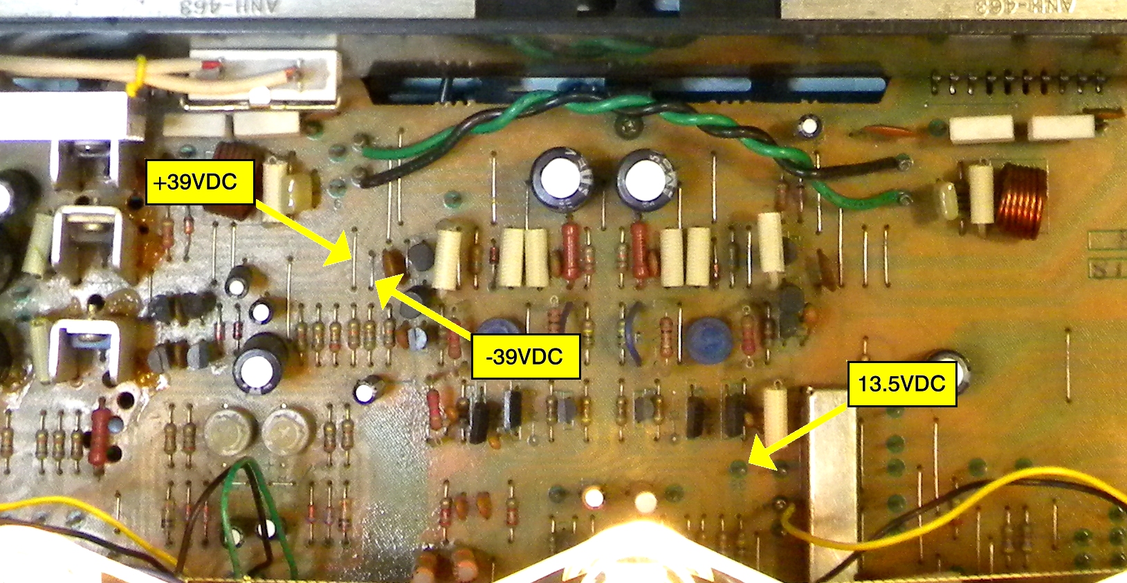
Would you point out where the +13v regulator is on the board? Is it at Q26? What measurements do you need to diagnose the problem?

Thank you for your advice.

Lou
 
Yes, Q26. Please measure and post all three of the leads' voltages referenced to a good chassis ground - That would be a good beginning.

If you review Mark's earlier post, it described attaching a small capacitor to one lead of the multimeter to filter DC and measure any residual AC voltage. Prepare one of the test leads in that manner and measure the AC voltage at the collector lead (case) of Q26 as well.
 
Q26 is the +13v regulator.
3 leads on the device, 3 voltage readings, plus Watthour's request to measure the tab voltage with a blocking capacitor.

actually, considering the SX-880's layout, measure all three with the blocking cap IN ADDITION TO the DC voltage measurements.

BE ULTRA CAREFUL NOT TO SHORT ANYTHING. insulate all but the tiniest portion of the tip of the probe(s).

upload_2022-3-2_16-58-50.png
 
Thank you both for responding to this vintage thread. I will try to buy the capacitor at my local Radio Shack or order it by mail. There used to be a nice electronics supply store in Manchester, but they have gone out of business. I'll get back to you as soon as possible with the voltage measurements.
 
I have not been able to buy that capacitor locally and will need to buy it online. Does it have to be a 1.0uF 250V Metal Film capacitor? Are there alternative specifications or types of capacitors that can fulfill the testing requirements? A friend has a bin of electronic parts that I can look through.
 
You can use any small cap, voltage rated to the voltage being checked.
You can also try it without a cap and post those measurements noting that the blocking cap is not installed.
If any AC is large enough to make a hum it might show without the cap :dunno:
I can send a cap if you need one.

Be very careful when probing. No extra work should be generated when troubleshooting. No shorts!

:lurk:
 
I have not been able to buy that capacitor locally and will need to buy it online. Does it have to be a 1.0uF 250V Metal Film capacitor? Are there alternative specifications or types of capacitors that can fulfill the testing requirements? A friend has a bin of electronic parts that I can look through.
the greater the capacitance (the bigger the cap) the better, although a 0.1uf 500v disc ceramic cap will get you into the game.

frankly, anything at or over 0.01uf and an appropriate voltage rating for what DC Voltage you are trying to block will do.
 
Here are the measurements I took this morning with FM on and tuned to a strong station:

Pin 60 -- 12.7v
Pin 7 -- 40v

I pulled a 470uF 25v cap out of an old cable modem and took some measurements with that cap in case it might be useful to you guys:

Pin 60 -- 10.8v
Pin 7 -- 38.5v

Finally, I wanted to mention that there is an awful lot of brown, bubbled gunk at the base of all the transistors on that board. Does that indicate that they have failed?

Thank you to Zebulon1 for offering to send me the proper cap. How can I send you my address in a private message?

regards,

Lou
 
Unfortunately, 470µF is a bit large to get what we are seeking. There is charging time involved when capacitance it that high, and that would tend to depress the RMS voltage reading of an AC wave.

Brown, hard residue is very likely the glue used in assembly to hold the larger components in place before wave soldering. Larger capacitors, cement resistors, larger transistors and their heat sinks, and other pieces with any appreciable mass were often glued on the assembly line before soldering. Some of that is visible here:

PioneerSX-780TestVoltage01.jpg
 
under one microfarad and NOT an electrolytic cap. gotta be some in there.
 
Here are the measurements I just took on the Q26 transistor (2SD712) without the cap. Zebulon1 will be sending me a cap by mail on Monday. Thank you very much. Per the online spec, Q26 is a NPN transistor with the poles labeled B, C, E. I think B is the center pole, but you all know more about this. So, here goes:

B -- 12.3v
C -- 11.7v
E -- 12.4v

Does this indicate a failed transistor? It will probably be a week before I can post the readings with the cap in place (unless I am able to get the cap from one of my local buddies).

Thanks again for your help and advice.

Lou
 
Last edited:
Please measure the voltage at both ends of R220. That's the cement resistor attached to the large heat sink in the unit.

Also, if you have another electrolytic capacitor, something larger than 50µF and over 50V, it may be useful for diagnosis shortly.
 
I did already measure the voltage going into that big resistor from pins 60 and 7 (12.7v and 40v). Are you asking me to measure the voltage at the board level rather than at the inputs to the resistor?
 
40v to 12.7v across 220 ohms at 5 watts infers 125 milliamps of current ( ~3.4w )

meanwhile, those transistor voltages stink.

they are so close together i can't tell if it's shorted or just not being turned on.

collector should be the largest of the three readings, greater than the base.
base
emitter should be 0.6v LESS than the base

might be instructive to remove it from circuit, and remeasure the empty collector, base and emitter connections
 
OK, I'll work on removing the transistor today and post the readings from the empty C, B, and E connections. I'm not sure I've identified the transistor leads correctly, but I think the center lead is the collector. I can also test the transistor using diode test feature on my DMM. I just watched a few YouTube videos on how to do that. Stay tuned for more measurements Thanks again.
 
Here are the latest test results with the transistor removed from the board. The transistor pins were all labelled on the board, so I have the correct layout now.

B -- 12.6v
C -- 47.4v
E -- -0.1v

Pin 7 -- 47.4v
Pin 60 -- 47.4v

I also tested the transistor with my DMM in diode mode following a test procedure I saw on YouTube.

With the black probe on Base:

B -- E 682
B -- C 678

With the red probe on Base:

B -- E No reading (Stays on 1)
B -- C No reading (Stays on 1)

Hope this helps with the troubleshooting. Thank you.
 
Back
Top Bottom