• The move to the new server is done. There are some software and database maintenance updates in process. This has us passing the hat around to help out. We appreciate any donations. Seriously, even a dollar helps. The payment page may be found here - https://www.audiokarma.org/support.html

Pioneer SX-880, FM Hum

get a new q26 (2sd712, npn), the diode mode tests can show faults but cannot confirm operation.

that base voltage is a bit low, i would get a new diode, too.

mouser.com:

512-1N5244B Fairchild 14 V, 0.5W Zener
78-TZX14C vishay 14 V, 0.5w, 2% low noise 0.19 ea

512-ksc2073tu
863-MJE15032G npn to-220 bce 250v 8a 50w 30mhz 70hfe $1.66
 
Would you please point out the location of the Zener diode that needs to be replaced?

Also, given that the unit is almost 50 years old, are there any other parts I should replace as a precaution? I realize that some people will do a complete rebuild and there are kits for this being sold on ebay. I don't think I'm up for a complete rebuild, but I am willing to replace critical components that are likely to fail soon.

As always, thank you very much for your troubleshooting advice.

SX-880-1.jpg SX-880-2.jpg
 
Hi Mark,
Are you also recommending that I replace the Q30 transistor? It's a 2SD325R-D. What is the Mouser replacement number for that transistor? Thanks again.
Lou
 
Hi Mark,
Are you also recommending that I replace the Q30 transistor? It's a 2SD325R-D. What is the Mouser replacement number for that transistor? Thanks again.
Lou

I found this thread with lots of info.
Mark had responded to it in some fashion.
https://audiokarma.org/forums/index.php?threads/sx-880-restoration-project.775405/

I think I would replace only what's needed at this point and get it running. See how your skills improve and if you want to continue. Its always best to repair first and then rebuild if that is the goal.
Let me know if you need any components, I can send them in an envelope.

Mark's recommendations form this thread, post #23:
Q30 2SD325 NPN TO-220C bce 35V 1.5A 10W 8MHz 40-320
512-KSC2073TU TO-220 bce 150V 1.5A 25W 4MHz 40-140

Q26 2SD712 NPN TO-220 bce 100V 4A 30W 8MHz 55-300
512-KSC2073TU TO-220 bce 150V 1.5A 25W 4MHz 40-140

D28 512-1N5244B Fairchild 14 V, 0.5W Zener
78-TZX14C vishay 14 V, 0.5w, 2% low noise 0.19 ea

:lurk:
 
a post of mine in this thread was lost - probably my harried and frazzled fault.
Q30 was only included as a landmark, and I did have a random thought that mentioning it might come back to bite me in the kazooo, it did....


Q30 can also be changed, and it uses either:
512-ksc2073tu
863-MJE15032G npn to-220 bce 250v 8a 50w 30mhz 70hfe $1.66
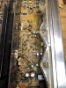
 
Hi Everyone,

I'm waiting for parts and will post an update once the transistors and Zener diode are installed. Thank you for all your help and advice.

Lou
 
I replaced transistors Q28 and Q30. I also temporarily replaced the D28 diode with a 13V Zener diode sent to me by a fellow member. I hope to have a 14V Zener diode soon. Unfortunately, the FM hum persists at the same level as before the replacements. Are there any other tests I should run to find the problem component? (I now have a 1uF 250V capacitor for testing purposes.) Thank you for your help.
 
Just for some clarification:
The hum is only when using the tuner? That's why the focus is on the 13.5v supply?
 
The hum is very loud in FM mode making it almost impossible to hear the FM broadcast. There is a very slight hum in Tape, AUX, and Phono mode, but it is almost imperceptible once the music starts playing through those inputs. Hope this clarification is helpful. Thanks for your advice on next steps.
 
measure the e,b & c voltages of your newly installed Q26.

Then take that 1uf 250v cap and connect it between your black dmm lead and the ground you are using for the readings.

Set the meter on AC volts
then remeasure the e,b & c voltages of your newly installed Q26.
keep on switching to more sensitive AC voltage ranges until you get an AC voltage reading.on each.

you haven't mention the type or model of your dmm, I need to know that to know what it's capabilities are.
 
Last edited:
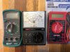
Attached is a picture of the 3 meters I own. I tend to use the green Commercial Electric DMM the most. However, it only has 2 AC settings. Hope that's OK. I'll post the results of the testing tomorrow. Thanks.

IMG_0358.jpg
 
Q26 and Q30 are the 2 recently installed transistors. When I tried to run the test recommended by Mark, the Commercial Electric DMM showed no AC readings for the transistors. It only has 2 AC settings -- 600V and 200V. Does this mean I need a better, more sensitive DMM? What model do you recommend? (I may be able to borrow a better DMM from a friend.)

Just for kicks, I took the 1uF capacitor out of the test and found the following AC measurements:

Q26
B -- 25.4v
C -- 26.9v
E -- 27.0v

Q30
B -- 62.0v
C -- 66.6v
E -- 90.5v
 
It is difficult to track a hum issue.
Search the web for other clues on how to trace down this elusive problem.
Most of the hum trouble I've encountered was found by luck and probing. Some was from poor decisions by me when securing the connections on the big filters.
General rules:
If the hum is heard in both speakers it a power supply problem.
If only one side its a amp or a pre amp problem.
If you can separate the amp and pre amp. Swap the channels. This will isolate the problem.
All the star grounds, the ones where the ground leads attach to a common chassis point should be visually checked for corrosion. By detaching the components and separating for a good visual check.
Poor or disconnected capacitors will cause a hum. Look for torn traces where you replaced the components. Many times the trace is torn but when checked with a meter it's open.
These hum issues can frustrate even the best of tech's.
If you come to the end of the road on you treasured receiver, send it to me and I'll fix it.
 
HI Bob,
Thank you for your advice. I'll do the visual checks you recommend and post the results here.

Also, in order to perform the AC measurements specified by Mark, I need a better, more sensitive DMM.

What kind of an AC range should the DMM have? Would you recommend a model?

Thank you.

Lou
 
I was able to borrow a Fluke 8022B DMM from a friend and take the AC measurements with the 1uF capacitor in place as recommended by Markthefixer. Here are the results for Q26 and Q30:

Q26 Q30
B 6.98v 8.62v
C 6.67v 8.99v
E 6.97v 8.65v

I took the measurements again after the unit had been on for a few minutes and got slightly different results:

Q26 Q30
B 7.32v 8.83v
C 7.34v 10.80v
E 7.38v 8.56v

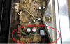
Attached is a picture of the bottom of the receiver. As suggested by zebulon1, I did not find any loose ground connections or evidence of defective solder joints. The hum continues to be very loud in both channels in FM mode and is very slight (almost imperceptible) in Aux, Tape, and Phono modes. I hope these new measurements help with the diagnosis. Thank you for your efforts to find root cause.
 

Attachments

  • SX-880-Bottom.jpg
    SX-880-Bottom.jpg
    203.5 KB · Views: 5
Last edited:
do you have 1n4004 diodes? 4 of them?

The numbers are so bad that I shudder. But we are at a point where I have to believe them.
and start thinking how can they get that way, and why does only the FM sound crappy andnothing else?

Take a picture of this area of the board, angled to show the board level components at the bottoms of the capacitors:

upload_2022-3-31_16-52-21.png
 
Last edited:
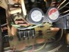
sx-880-angle.jpg I don't have any diodes in stock. Here is a picture of the components below the capacitors. It is not much better than what you circled in red. Are you trying to see the components behind the green and black wires? Please let me know what you need. Thanks. Lou
 
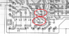
upload_2022-4-1_15-25-24.png

yes
D24, D25, D26 D27.

the wonder is that why hum is not more prevalent.

4 new diodes and C407 / C408 ?
 
Last edited:
Would you explain why you concluded C407, C408, and D24 - D27 need to be replaced? Also, would you circle the location of the 4 diodes?

Thank you. I'll get the parts and let you know the outcome.
 
Back
Top Bottom