

You are using an out of date browser. It may not display this or other websites correctly.
You should upgrade or use an alternative browser.
You should upgrade or use an alternative browser.
Pioneer SX-950 Restoration Project
- Thread starter Timothy Flath
- Start date


Timothy Flath
Well-Known Member
On it - ordering one Omron and a spare from Newark (they ship faster to Canada here) - getting the LY with standoffs noted in another thread. Thank you.Just replace the relay. Cleaning them is a waste of time and I don’t recommend it.
Timothy Flath
Well-Known Member
Well folks, so far it is a bust. Need some help. Issues so complicated I thought I would film an explanation video. After this post I will post a clip of the voltages I am getting from the power supply board (Forgot to mention that I was able to set the DC offset and bias for both channels as per the manual after doing the changes I mentioned - settings were stable). Anyway here is the story of my woes and why I think it is a PS Board issue:
Timothy Flath
Well-Known Member
Here are the voltage readings on the board:
https://timothyflath.smugmug.com/Stereo/Pioneer-Stuff/SX-950/i-zr4TmCX/A
https://timothyflath.smugmug.com/Stereo/Pioneer-Stuff/SX-950/i-zr4TmCX/A

The salient fact is that the 51v regulated is only 37, while the series regulator is being fed 39v, and the AC off the transformer is 33v.(pin 25 & pin 26)
WHY this is happening... are you still on DBT? Is it a multi-voltage unit? If a wire broke in the primary of a multi-voltage unit, it could result in this.
The 7.5vac lamp circuit is monitored by the protect to determine turn-on and turn off status. These AC voltages aren't enough to say "I'm ON !!"... to the protect board. (pin 12, what is the AC voltage?)
WHY this is happening... are you still on DBT? Is it a multi-voltage unit? If a wire broke in the primary of a multi-voltage unit, it could result in this.
The 7.5vac lamp circuit is monitored by the protect to determine turn-on and turn off status. These AC voltages aren't enough to say "I'm ON !!"... to the protect board. (pin 12, what is the AC voltage?)
Last edited:
Timothy Flath
Well-Known Member
Thank you for responding Mark. Have seen many threads you have provided your sage advice in. Out for dinner now. Have not checked if it is a multi-voltage unit at this juncture but will when I get home. I used to sell hifi overseas in the military market many many moons ago and a lot of that gear came back to Canada here so it is entirely possible - yes, still on dbt. Didn't want to pull it off given it still had a fair bit of glow on the bulb. Didn't want to risk frapping something before someone wiser than I provided a responseThe salient fact is that the 51v regulated is only 37, while the series regulator is being fed 39v, and the AC off the transformer is 33v.(pin 25 & pin 26)
WHY this is happening... are you still on DBT? Is it a multi-voltage unit? If a wire broke in the primary of a multi-voltage unit, it could result in this.
The 7.5vac lamp circuit is monitored by the protect to determine turn-on and turn off status. These AC voltages aren't enough to say "I'm ON !!"... to the protect board. (pin 12, what is the AC voltage?)

Last edited:
Timothy Flath
Well-Known Member
Back now - Restaraunt was full so did take out
North American voltage only . Never even considered that it might be the transformer that is duff Never had one go south on me and I also found it very odd that the service manual does not specify the voltages we should be seeing off the secondary windings?
I may have missed it in the Manual but I did look fairly hard
North American voltage only . Never even considered that it might be the transformer that is duff
Never had one go south on me and I also found it very odd that the service manual does not specify the voltages we should be seeing off the secondary windings?I may have missed it in the Manual but I did look fairly hard
Last edited:
Those missing AC secondary voltages in the manuals always REALLY irked me.
I haven't seen many transformers actually fail, but I have seen a few that are fed wrong or strangled.
Once the power output transistors are installed and idle currents tested ("tickling the dragon's tail"), there is no point in leaving the DBT connected.
I haven't seen many transformers actually fail, but I have seen a few that are fed wrong or strangled.
Once the power output transistors are installed and idle currents tested ("tickling the dragon's tail"), there is no point in leaving the DBT connected.
Timothy Flath
Well-Known Member
Meant to say it is 120 VAC 60 Hz 370 watts only. I edited the previous response to say it was single voltage unit. Anyway I gather that the transformer output needs to be at least 50V off the feed to the D1-4 Bridge voltage regulator? Still trying to process how it is that the feed AC voltage is close to the same on both taps and they are close to the same? Is it because I still have it plugged to the DBT and somehow current limiting is limiting voltage too?Those missing AC secondary voltages in the manuals always REALLY irked me.
I haven't seen many transformers actually fail, but I have seen a few that are fed wrong or strangled.
Thanks
Tim
Last edited:
Timothy Flath
Well-Known Member
Just found this thread with your input. At first glance it looks pretty similar so will have a read through so as not to reinvent the wheel: https://audiokarma.org/forums/index.php?threads/pioneer-sx-950-power-measurement-issues.917986/Those missing AC secondary voltages in the manuals always REALLY irked me.
I haven't seen many transformers actually fail, but I have seen a few that are fed wrong or strangled.
Once the power output transistors are installed and idle currents tested ("tickling the dragon's tail"), there is no point in leaving the DBT connected.
Yes. The DBT strangles the unit, although the more wattage of the DBT, the less the strangling. The larger wattage doesn't really affect the vital function of the DBT, because when the DBT is bright, the unit is super strangled.
Since you said that idle current checked ok (on dbt no less) be sure the idles are dialled down to zero, then get off the DBT.
IF idle current is set on DBT, AND LEFT AT THAT SETTING, when the unit is plugged into the wall directly, the idle currents will be wayyyy too high. Perhaps damagingly high.
Remember, the unit was being strangled (ON dbt) , and as the idle current (on dbt) is turned up, the strangling becomes more pronounced.
Since you said that idle current checked ok (on dbt no less) be sure the idles are dialled down to zero, then get off the DBT.
IF idle current is set on DBT, AND LEFT AT THAT SETTING, when the unit is plugged into the wall directly, the idle currents will be wayyyy too high. Perhaps damagingly high.
Remember, the unit was being strangled (ON dbt) , and as the idle current (on dbt) is turned up, the strangling becomes more pronounced.
Timothy Flath
Well-Known Member
Thought as much. I actually set the DC offset and bias when the receiver was off the DBT. Reading that previous thread I have pulled the PS fuses and am going to try to get AC Voltage readings from the board inputs. Will do it 1st on DBT then risk going off DBT. So far I have not put the shunts back in between the pre out and main in sections of the receiver. Have also got the speaker selectors switched off to isolate the amp side as best I can. Taking baby steps me thinks....Yes. The DBT strangles the unit, although the more wattage of the DBT, the less the strangling. The larger wattage doesn't really affect the vital function of the DBT, because when the DBT is bright, the unit is super strangled.
Since you said that idle current checked ok (on dbt no less) be sure the idles are dialled down to zero, then get off the DBT.
IF idle current is set on DBT, AND LEFT AT THAT SETTING, when the unit is plugged into the wall directly, the idle currents will be wayyyy too high. Perhaps damagingly high.
Remember, the unit was being strangled (ON dbt) , and as the idle current (on dbt) is turned up, the strangling becomes more pronounced.
Timothy Flath
Well-Known Member
On DBT with no fuses in
PIN 24: 7.95 VAC
PIN 25: 46.50 VAC
PIN 26: 46.54 VAC
PIN 27: 19.6 VAC
PIN 28: 19.60 VAC
PIN 24: 7.95 VAC
PIN 25: 46.50 VAC
PIN 26: 46.54 VAC
PIN 27: 19.6 VAC
PIN 28: 19.60 VAC
Timothy Flath
Well-Known Member
Off DBT with no fuses in
PIN 24: 8.22 VAC
PIN 25: 48.05 VAC
PIN 26: 48.05 VAC
PIN 27: 20.03 VAC
PIN 28: 20.03 VAC
PIN 24: 8.22 VAC
PIN 25: 48.05 VAC
PIN 26: 48.05 VAC
PIN 27: 20.03 VAC
PIN 28: 20.03 VAC
Timothy Flath
Well-Known Member
Here goes with fuses in and DBT out
Results to follow
Results to follow
Timothy Flath
Well-Known Member
Fingers remain crossed. Here is what actually happened first hand:
Last edited:
Timothy Flath
Well-Known Member
I rotated the Bias offset trimmers fully counter clockwise to start just to heed the warnings. Here are my numbers from the above video ( yeah was reading AC at first):
1: 0V
2: 6.46V 1.25VAC variable
3: 6.51V 1.30 VAC variable
4: 13.50V
5: 13.51V
6: 50.92V
7: 50.93V
8: 35.46V
9: 35.47V
10: 27.36V
11: 27.36V
12: 0V
13: -14.42V
14: -54.38V
15: -20.71
Holy smokes - the numbers are a super close match to the original numbers I had when the receiver was working after my Part 9 video in the thread above. Pins 2 and 3 show it settles down to 1.2ish VAC... Is this normal having AC bleed through a bit here (and only on these two pins)? All other pins read zero for AC. Puzzling? I presume not a big deal since it is indicator lights and switch assemblies AWR-094/095? Next step I think is to reset DC offset to 0 ( see if it drifted after warmup) and to bring biasing to 20mA....
Hopefully that goes good. Still worried something intermittant is going on
):1: 0V
2: 6.46V 1.25VAC variable
3: 6.51V 1.30 VAC variable
4: 13.50V
5: 13.51V
6: 50.92V
7: 50.93V
8: 35.46V
9: 35.47V
10: 27.36V
11: 27.36V
12: 0V
13: -14.42V
14: -54.38V
15: -20.71
Holy smokes - the numbers are a super close match to the original numbers I had when the receiver was working after my Part 9 video in the thread above. Pins 2 and 3 show it settles down to 1.2ish VAC... Is this normal having AC bleed through a bit here (and only on these two pins)? All other pins read zero for AC. Puzzling? I presume not a big deal since it is indicator lights and switch assemblies AWR-094/095? Next step I think is to reset DC offset to 0 ( see if it drifted after warmup) and to bring biasing to 20mA....
Hopefully that goes good. Still worried something intermittant is going on
Last edited:
I have a problem with your entries,, you use a dash as a separator, but there are also negative voltages to be recorded. I assume dash space is a separator while dash number is a negative voltage.
2 & 3 are the function lamps, and if they have been changed from the 50mA incandescent lamps there will be a difference.
otherwise pins 27 & 28 feed ac to D9 & D10 through FU4 & FU5 to C12 1000uf / 35v
Since the 13.5v at pins 4 & 5 is ok, I suspect a problem with R20. R21, R22, Q9, Q10, C14 & or C13. See how stable the base voltage of Q10 is.
It should be mumble mumble {13.24 + 0.6 = 13.8 13.8 x (R22/(R21 + R22))) = 6.325 6.325 - 0.6 - 0.6 = 5.125 } 5.125 at pins 2 & 3 / base voltage of 6.325 .
Offset will be different, the power supply voltages changed.
2 & 3 are the function lamps, and if they have been changed from the 50mA incandescent lamps there will be a difference.
otherwise pins 27 & 28 feed ac to D9 & D10 through FU4 & FU5 to C12 1000uf / 35v
Since the 13.5v at pins 4 & 5 is ok, I suspect a problem with R20. R21, R22, Q9, Q10, C14 & or C13. See how stable the base voltage of Q10 is.
It should be mumble mumble {13.24 + 0.6 = 13.8 13.8 x (R22/(R21 + R22))) = 6.325 6.325 - 0.6 - 0.6 = 5.125 } 5.125 at pins 2 & 3 / base voltage of 6.325 .
Offset will be different, the power supply voltages changed.
Timothy Flath
Well-Known Member
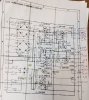
This image shows the values (in black) I measured when the receiver was working after I did the PS board and when I completed the Part 9 video (posted earlier in this thread) - Receiver was in use for a month before I replaced the old trimmers with new, changed out the relay, swapped out the Mpx switches on that switch board, and then set the DC Offset to zero and bias to 20mA. The values in red are what I am getting now and are much different than my previous bad readings in the thread previously. The only unknown is I didnt really do anything different since those bad readinngs Except:
- Pulled the fuses to test on DBT and off DBT
- remove and tested ZD-1 and put back in
- removed and test the lower two diodes on the board from the D1-D4 bridge. Both tested good so were replaced on the board
- found a lose wire connecting pin 10 on PS Board and a pin 10 on the protection board. Pretty sure this disconnected when I was man-handling the board to do the 2 bullets above
- replaced thermal grease and tested all output transistors. Note one channel is all original Toshiba Trannys and the other channel look to be matched NEC brand trannys.
I still have no idea what changed things to get these new better readings in line with previous so hoping it is not an intermittant fault...
Here goes (see attached image)
- Pulled the fuses to test on DBT and off DBT
- remove and tested ZD-1 and put back in
- removed and test the lower two diodes on the board from the D1-D4 bridge. Both tested good so were replaced on the board
- found a lose wire connecting pin 10 on PS Board and a pin 10 on the protection board. Pretty sure this disconnected when I was man-handling the board to do the 2 bullets above
- replaced thermal grease and tested all output transistors. Note one channel is all original Toshiba Trannys and the other channel look to be matched NEC brand trannys.
I still have no idea what changed things to get these new better readings in line with previous so hoping it is not an intermittant fault...
Here goes (see attached image)
Attachments
Last edited:
Timothy Flath
Well-Known Member
Thanks agaon for the feedback. Having trouble deciphering your formula but will try to think it through.I have a problem with your entries,, you use a dash as a separator, but there are also negative voltages to be recorded. I assume dash space is a separator while dash number is a negative voltage.
2 & 3 are the function lamps, and if they have been changed from the 50mA incandescent lamps there will be a difference.
otherwise pins 27 & 28 feed ac to D9 & D10 through FU4 & FU5 to C12 1000uf / 35v
Since the 13.5v at pins 4 & 5 is ok, I suspect a problem with R20. R21, R22, Q9, Q10, C14 & or C13. See how stable the base voltage of Q10 is.
It should be mumble mumble {13.24 + 0.6 = 13.8 13.8 x (R22/(R21 + R22))) = 6.325 6.325 - 0.6 - 0.6 = 5.125 } 5.125 at pins 2 & 3 / base voltage of 6.325 .
Offset will be different, the power supply voltages changed.
Fixed confusing list - I had changed to colons after the pin number where values were neg - I got lazy and didn't go back and fix it for the previous pin numbers which made them all look like neg values. Fixed now by editing the post. Thanks for pointing this out.
All indicator lights in the unit were switched to LED during the restoration because most originals were burned out when I got the unit and some of the bayonet mount shrouds were missing. This receiver was definitel worked on previously for sure. It was a LED light kit I bought from NYC via ebay specifically for the SX-950 so I thought the current draw would be similar to the original lights - guess not (makes sense given LEDs draw differently than Incandescent)?
Getting late here on the west coast (Vancouver Island - Victoria, BC) so will delve into the rest tomorrow. Your comments are very much appreciated. All the caps and AK recommended Trannys were swapped out as part of this video clip (could be I toasted some items so will check all those components out and the tranny lead values):
Last edited: