• The move to the new server is done. There are some software and database maintenance updates in process. This has us passing the hat around to help out. We appreciate any donations. Seriously, even a dollar helps. The payment page may be found here - https://www.audiokarma.org/support.html

Pioneer SX-950 wont come out of protection

CavScout

Super Member
Hi folks

I am hoping some of the experts out there can assist me with a problem I am having.

I just bought an SX-950 and the unit will not come out of protection at all.

I hooked up a DBT and there are no shorts.

I would like to start with the simple stuff so.......
Is it possible if I remove it and deox it that it will work or ???

Any assistance is greatly appreciated

Thanks
 
Register to hide this ad
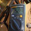
I have a basic Fluke multimeter. What do I set it to?
Do I put the black to the stereo frame as ground?
What readings am I looking for?
Thanks for your help
 
You will need to find & download the service manual for this model.

Set the meter to DC mV.

You will need to measure the DC mV (very carefully) at the points petehall refers to - these will measure the DC offset at the amount going into the speaker protect relay side.
 
Go to hifiengine.com and download the service manual.
Read it, check the dc offset and bias as described therein.
 
Thanks folks.
I am not very good at reading elec schematics at all.
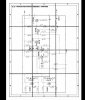
But I do see 8 voltages referred to on that page .

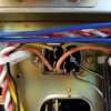
There are 4 pins that are bridged and 2 that are single.

The voltages that I see on that page are
36.5

1.0
7.5
13.5
5.1
0.6
0.6
0.7

So there are references to 8 voltages but 10 pins (including the bridges.......and I would assume each bridge would have equal voltage reading)

Also, silly question guys but... I hold the red to the test point and clip the black to the frame of the unit right ?
 

Attachments

  • 20180704_182057.jpg
    20180704_182057.jpg
    50.5 KB · Views: 35
  • 20180704_175232.jpg
    20180704_175232.jpg
    50.7 KB · Views: 36
That's an easy one - ON.
But be careful not to short out any pins while taking measurements.
Your ground lead goes to the chassis.

So when I tested it with the unit off the readings were falling fast until zero.
I guess this is because the caps behind these readings are dumping to the frame?
 
The Mv AC readings that I got were

From the 2 orange wire connections
67.5
377.0 ( very erratic)

From the 2 yellow wire connections
71.2
97.1

From the grey wire (to a single pin)
10.3

From the black/white wire (to a single pin)
0.5
 
So when I tested it with the unit off the readings were falling fast until zero.
I guess this is because the caps behind these readings are dumping to the frame?

Yeah you need the unit on for testing voltage and usually off for resistance etc
 
The Mv AC readings that I got were

From the 2 orange wire connections
67.5
377.0 ( very erratic)

From the 2 yellow wire connections
71.2
97.1

From the grey wire (to a single pin)
10.3

From the black/white wire (to a single pin)
0.5

Hopefully those were mV DC :-)
 
The wire wrap connection pins have numbers assigned to them. It would help to know what voltages are a which pins, since colors are not always consistent. For example, Pins 1 should normally be at or below 0.010VD, Pin 2 should be around 13V (-), Pin 3 should be at or below 0.010VDC, etc.
 
Back
Top Bottom