• The move to the new server is done. There are some software and database maintenance updates in process. This has us passing the hat around to help out. We appreciate any donations. Seriously, even a dollar helps. The payment page may be found here - https://www.audiokarma.org/support.html

Pioneer SX 980 - Blow up fuse

Frederic73

New Member
Hi All

Bought a pioneer SX980 from Thailand and Im in Australia

Made the dumbest mistakes of not checking the voltage and just power it on

OF course it blew up the backplane Fuse and smokes from PS board

It was set to 220V and here in OZ we use 240V. Is that why it really blew up ?

I did switch it back to 240V and put a new 3Amp fuse and no smoke or fuse blowing up

But also no power or relay click at all

So what are my next steps. ?

Should i remove the PS board and recap and check all components . I was meant to slowly recap it anyway

Thanks
 
Register to hide this ad
It is very unlikely that powering a unit set for 220 with 240 volts would cause any damage at all. That voltage is not even 10% too high. Now powering one set for 117 or 120 volts on 240 would very likely cause damage.
 
So what are my next steps. ?
I agree with @AE Bob. It’s unlikely that voltage difference would release magic smoke, but who knows.

First step is to check power supply voltages. With luck the fuses did their job and limited any damage was limited to the PS board.
 
My thought also. All the fuses on the Power supply board are still intact.

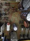
A few bloated caps

I have ordered a rebuild kit for that board and will start from there
 
Hi

Got my rebuild kit https://www.ebay.com.au/itm/123706590812

And working my way until i came across a 3 leg 35v 2200uf cap

Do i just ignore the middle pin when replacing with a 2 pin cap ??
If you look at the circuit board pic you provided you'll see the outer two leads go to different places in the circuit. The middle one connects to nothing.

It is only there to hold the cap in place. Very common.
 
Hi all

Recapped done and i also replaced a few transistors and diodes on the power supply and protection board

The Good news is it does power on and nothing blew in my face

The bad news is there is no click and no sound. where did i screw up ???

Power Supply

Pin 20 38.04v no wires attached to it
Pin 22 55V
Pin 23 24.20v
Pin 24 24.21v
Pin 25 -23.50v
Pin 26 -23.60v
Pin 27 -49.90v
Pin 28 -12.90 No wires attached to it


Protection board

Pin 1 21.35 AC
Pin 2 -49.65 v
Pin 4 13v
Pin 5 0.145v
Pin 7 0.066v
Pin 8 0.023v
Pin 9 0.020v
Pin 10 70.2


Parts used

c2073 transistors
A940 transistors
ksc2383 transistors
ksa1013 transistors
1N4004
1N5404
244b glass diode
D243B glass diode
4748 glass diode


protection board
A992 transistor
c2690 transistor
d243b diode
 
On Pin 16 on power supply im getting 10.20V
On Q5 which has been replaced with a C2073 transistor ,

B 13.17v
C 25.60V
E 13.76 v
 

Attachments

  • C2073.jpg
    C2073.jpg
    101.7 KB · Views: 3
Pin 16 is connected to emitter Q5. Voltage shoud be the same.

Pin 16 connects to pin 9 protection where you show .020V. Voltage should be same (13V). You need 13V on pin 9 of protection circuit.

What is the voltage on pins 17&18 of power supply?
 
Last edited:
Pin 16 is connected to emitter Q5. Voltage shoud be the same.

Pin 16 connects to pin 9 protection where you show .020V. Voltage should be same (13V). You need 13V on pin 9 of protection circuit.

What is the voltage on pins 17&18 of power supply?
Weird , now im getting

Pin 16 - 13.12V
Pin 17 -13.88v
18 - 7.46 v
 
here we go

Thanks for all your help

pin 1 21.40 v Ac
2 -49.60 v
3 0v
4 12.79v
5 0.149v
6 0.103v
7 0.067v
8 0.021v
9 13.22v
10 68.6v
 
Back
Top Bottom