Chammycaps28
New Member
Hi everyone! This is my first repair post so please be gentle with me haha.
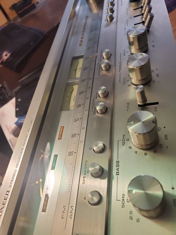
So a few months back I picked up a pioneer sx-1250 reciever and a sg-9500 equalizer from a rather sketchy man. I was told I could test them and that they worked great.......we've all heard that story before haha. so I show up and the house is a shack that is half torn down, with no water or power. And the gear is piled up on a cardboard box. The faceplate on the 1250 was gouged because the previous owner used a steak knife or a coat hanger to push the buttons in, and all the buttons were jammed in. And the eq had a cut off power cord. Needless to say I didn't test them. The price was cheap enough at $475 for both and the 1950s mid century kitchen from the house he was tearing down. SCORE!
So I restored the faceplate and the buttons, luckily none wore broken. And the faceplate came out scratch free.
Opened it up to check the 4 big caps, and they puked all over the bottom plate. So it was time for a rebuild. I did the following.
I replaced all electrolytic caps, tantalum caps and Transistors that were on the shoot on sight list.
The big caps came from China, and were restuffed into the original cans.
3 watt resistors on aw-106 board, protection board and power supply board upgraded from 3 watt to 5 watt.
Damage it exhibited when I got it
Awr-106 board
One transistor, 2sd325r was fried. Replaced with b31c2073.
2 resistors fried. Hot spot on half the board. Components tested fine and within spec. Except for the two resistors
Tested all tantalum caps, diodes and transistors including those that were removed, all tested fine, as per the diode test function on my multimeter.
Deoxited all pots, and switches.
Touched up all suspicious solder joints.
Tested all 8 output transistors. 7 read strong, one read on the weak side but still within spec. New mica sheets and thermal grease.
So I went to power it on, on a dim bulb tester with a 100 watt bulb.aw-048 boards disconnected top and bottom, jumpers disconnected in back. Bright bulb and no lights. No engagement from soft start relay, or protection relay
Fuses tested fine, with continuity
Thermosistor testeded fine with continuity
Soft start resistor tested fine at 3.5 ohms
Voltage readings were as follows:
At power cord coming in: 3.1vac on hot side and 1.9 on nutral.
Power supply: awr-107
Pin 1: .86vac
Pin 2: 2.22 vac
Pin 8: .51vdc
Pin 9: 2.26vdc
Pin 10: -2.06vdc
PIN 13: 1.20vdc
Stabilizer board:
Pin 1: -4.7 vdc
Pin 2: .9 vdc
Pin 3: 0 vdc
Pin 4: 1.6 vac
pin 5: 1.6 vac
Pin 6: 0 vdc
Pin 7: 0 vdc
Pin 8:0 vdc
Pin 9: 0 vdc
pin 10:0 vdc
Pin 11:0vdc
Pin 12: 0vdc
Pin 13: 0vdc
Pin 14: 0vdc
Pin 15: 0 vdc
Pin 16: 0vdc
Pin 17: 0vdc
Disconnected red plug to transformer on stabilizer board, still bright.
Disconnected plug underneath with white and brown wires going to the filter
caps and output transistors, still bright.
Disconnected red and orange plug on the protection board going to filter caps and output transistors, still bright.
Disconnected purple plug from transformer, to protection board. Went dim lights on left side came on. Powered up. Both relays clicked.
It will stay on and the light will remain dim aslong as the purple plug on the protection board and the brown and white plug on the stabilizer board are removed. Also Removed filter caps from circuit, no change.
voltage readings with purple plug and white/brown plug removed are as follows:
Power cord hot: 62.6 vac
Power cord nutral: 20.4 vac
Power supply awr-107:
Pin 1: 20.4 vac
Pin 2: 20.4 vac
Pin 8: 15.2 vdc
Pin 9: 55.1 vdc
Pin 10: -57 vdc
Pin 13: 30.2 vdc
Stabilizer board:
Pin 1: -0.47 vdc
Pin 2: 0 vdc
Pin 3: 0 vdc
Pin 4: 38.2 vac
pin 5: 38.2 vac
Pin 6: 55.4 vdc
Pin 7: 15.3 vdc
Pin 8: 7.6 vdc
Pin 9: 13.3 vdc
pin 10: 23.5 vdc
Pin 11:54 vdc
Pin 12: 0vdc
Pin 13: 56 vdc
Pin 14:23.3 vdc
Pin 15: -57.3 vdc
Pin 16: -59.8 vdc
Pin 17: 54 vdc.
These are the voltages that I got from both boards, under both conditions. I know that this post is very long winded, and I apologize for that, but you guys are unstoppable with the correct information. So I wanted to give you the best info I could. I will gratefully appreciate any help I get on getting this fixed.
Thank you everyone, I will get the voltages on the protection board tomorrow
,
So a few months back I picked up a pioneer sx-1250 reciever and a sg-9500 equalizer from a rather sketchy man. I was told I could test them and that they worked great.......we've all heard that story before haha. so I show up and the house is a shack that is half torn down, with no water or power. And the gear is piled up on a cardboard box. The faceplate on the 1250 was gouged because the previous owner used a steak knife or a coat hanger to push the buttons in, and all the buttons were jammed in. And the eq had a cut off power cord. Needless to say I didn't test them. The price was cheap enough at $475 for both and the 1950s mid century kitchen from the house he was tearing down. SCORE!
So I restored the faceplate and the buttons, luckily none wore broken. And the faceplate came out scratch free.
Opened it up to check the 4 big caps, and they puked all over the bottom plate. So it was time for a rebuild. I did the following.
I replaced all electrolytic caps, tantalum caps and Transistors that were on the shoot on sight list.
The big caps came from China, and were restuffed into the original cans.
3 watt resistors on aw-106 board, protection board and power supply board upgraded from 3 watt to 5 watt.
Damage it exhibited when I got it
Awr-106 board
One transistor, 2sd325r was fried. Replaced with b31c2073.
2 resistors fried. Hot spot on half the board. Components tested fine and within spec. Except for the two resistors
Tested all tantalum caps, diodes and transistors including those that were removed, all tested fine, as per the diode test function on my multimeter.
Deoxited all pots, and switches.
Touched up all suspicious solder joints.
Tested all 8 output transistors. 7 read strong, one read on the weak side but still within spec. New mica sheets and thermal grease.
So I went to power it on, on a dim bulb tester with a 100 watt bulb.aw-048 boards disconnected top and bottom, jumpers disconnected in back. Bright bulb and no lights. No engagement from soft start relay, or protection relay
Fuses tested fine, with continuity
Thermosistor testeded fine with continuity
Soft start resistor tested fine at 3.5 ohms
Voltage readings were as follows:
At power cord coming in: 3.1vac on hot side and 1.9 on nutral.
Power supply: awr-107
Pin 1: .86vac
Pin 2: 2.22 vac
Pin 8: .51vdc
Pin 9: 2.26vdc
Pin 10: -2.06vdc
PIN 13: 1.20vdc
Stabilizer board:
Pin 1: -4.7 vdc
Pin 2: .9 vdc
Pin 3: 0 vdc
Pin 4: 1.6 vac
pin 5: 1.6 vac
Pin 6: 0 vdc
Pin 7: 0 vdc
Pin 8:0 vdc
Pin 9: 0 vdc
pin 10:0 vdc
Pin 11:0vdc
Pin 12: 0vdc
Pin 13: 0vdc
Pin 14: 0vdc
Pin 15: 0 vdc
Pin 16: 0vdc
Pin 17: 0vdc
Disconnected red plug to transformer on stabilizer board, still bright.
Disconnected plug underneath with white and brown wires going to the filter
caps and output transistors, still bright.
Disconnected red and orange plug on the protection board going to filter caps and output transistors, still bright.
Disconnected purple plug from transformer, to protection board. Went dim lights on left side came on. Powered up. Both relays clicked.
It will stay on and the light will remain dim aslong as the purple plug on the protection board and the brown and white plug on the stabilizer board are removed. Also Removed filter caps from circuit, no change.
voltage readings with purple plug and white/brown plug removed are as follows:
Power cord hot: 62.6 vac
Power cord nutral: 20.4 vac
Power supply awr-107:
Pin 1: 20.4 vac
Pin 2: 20.4 vac
Pin 8: 15.2 vdc
Pin 9: 55.1 vdc
Pin 10: -57 vdc
Pin 13: 30.2 vdc
Stabilizer board:
Pin 1: -0.47 vdc
Pin 2: 0 vdc
Pin 3: 0 vdc
Pin 4: 38.2 vac
pin 5: 38.2 vac
Pin 6: 55.4 vdc
Pin 7: 15.3 vdc
Pin 8: 7.6 vdc
Pin 9: 13.3 vdc
pin 10: 23.5 vdc
Pin 11:54 vdc
Pin 12: 0vdc
Pin 13: 56 vdc
Pin 14:23.3 vdc
Pin 15: -57.3 vdc
Pin 16: -59.8 vdc
Pin 17: 54 vdc.
These are the voltages that I got from both boards, under both conditions. I know that this post is very long winded, and I apologize for that, but you guys are unstoppable with the correct information. So I wanted to give you the best info I could. I will gratefully appreciate any help I get on getting this fixed.
Thank you everyone, I will get the voltages on the protection board tomorrow
,