• The move to the new server is done. There are some software and database maintenance updates in process. This has us passing the hat around to help out. We appreciate any donations. Seriously, even a dollar helps. The payment page may be found here - https://www.audiokarma.org/support.html

Pitiful X-202

Thanks for inputs input on the 202! And the remote issues with the 500.

As for the faceplate on yours--they're only original once. Mine has tarnish and some scratches but it's the history of the unit, not my history. If I were to find a NOS plate, I'd swap it out, but that will never happen.
 
As I mentioned to Frannie, I think that's where I am as well. The existing face plate adds character. It really is coming along nicely. I should have some more pics later on tonight.

Dave
 
More Progress

For this project, today was a day of details. The low voltage DC supply was all finished up, and the DC bias and balance controls have all been set to initial settings. With the way the previous repair work had been done, this took much more time than it should have. Original wiring was cut when that repair job was implemented, and other portions were burned from age or the poor repair. Rather than extend the old wiring or simply cut out the bad portions, the affected wiring was completely removed and new installed. Fishing the new wire where the old originally was takes time. But, the resulting job looks about as factory as possible, and is certainly more dependable that what was there.

Additionally, wiring for the Phase Reverse switch was reinstalled, the jumpers added to the Remote Control socket were uninstalled, the Phase Inverter controls were preset, and the wiring was generally cleaned up.

Power was then applied (for the first time) with all tubes except the rectifier to check AC heater voltage, and the output from the low voltage DC supply for the small signal tubes and output tube bias. Everything behaved and worked as it was supposed to with proper voltage to all heaters, and smooth action in all of the DC Bias and Balance controls.

Output tubes were then removed, and a 5Y3 installed to check the condition of the second can cap and add on phono decoupling cap. These caps appear original, but show no signs of deterioration at this point. All measured respectably close to value, with no signs of pressure build up from internal breakdown. Indeed, they all formed very quickly, and a leak down test proved out the lack of internal leakage. What a nice surprise! Still, these caps are on the list to be replaced, but for now, are fine for the project's current status.

Pics include:

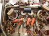
1. The new low voltage DC heater/bias supply has now been completely reworked. The can cap for this supply had been replaced relatively recently and was still good. But it was only a single section cap, requiring the add on cap which is now properly anchored to the chassis, all while not covering the vent holes in the process. The dropping resistor is now a factory spec part, with all surrounding components giving it a wide birth due to the heat it radiates. To facilitate a neat installation, the end of the T-strip on upper deck (that originally had its mid portion burned out from the B+ power resistors attached to it) that was still mounted to the chassis (but serving no purpose now) was removed by drilling out the rivet holding it in place, and a different T-strip installed (by nut and bolt) to eliminate any "air" connections.

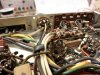
2. New wires were pulled to restore operation of the Phase Reverse switch. This required the complete removal/reinstallation of the spiral spring shield that the original wiring for this switch ran through on the top of the chassis. Can you say Chinese Finger Torture? That's about what the process amounted to!

3. The jumpers shorting across the Remote Volume Control jack were removed, and the general output stage wiring tidied up. Individual cathode resistors still need to be installed at this point.

4. Even the braided wire connecting the phono preamp tube sockets was missing when received (ripped out), so new braid was installed. Without this braid, the frame of the tube sockets and their shields would not be grounded, since the sockets are mounted by grommets to reduce the chance of microphonic feedback. The result would be notably increased hum from the phono preamps. In so many ways, its the details that make a Fisher a Fisher, so attending to them properly is an important part of making any Fisher perform as it was intended to.

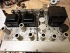
5. Heck, just adding some tubes and shields makes the poor thing look better by leaps and bounds.

A few more details to address, and I'm still waiting on the new power switch from Mark. Once that arrives, the volume control/loudness switch assembly can be reinstalled. Then, I should be very close to a full power start up and checkout.

Dave
 

Attachments

  • X-202 Progress 002.jpg
    X-202 Progress 002.jpg
    128.8 KB · Views: 178
  • X-202 Progress 009.jpg
    X-202 Progress 009.jpg
    105.1 KB · Views: 167
  • X-202 Progress 010.jpg
    X-202 Progress 010.jpg
    86.4 KB · Views: 165
  • X-202 Progress 003.jpg
    X-202 Progress 003.jpg
    71.6 KB · Views: 158
  • X-202 Progress 001.jpg
    X-202 Progress 001.jpg
    83.4 KB · Views: 174
I will be keeping an eye on this thread...

Sucks about the face plate but I guess it goes along with playing around with these 50 some year old units. Mine normally resides in my console, the plate is in a bit nicer shape but I am missing five out of the six jewels.

I have posted to a couple of these thread over the years in regard to the opt's versus the ones from the SA-100 to never get any sort of interest or answer, thanks for clearing that up, it was my suspicion.
 
Will be watching this thread as well...Perch there jewels for sale on the auction site, they are good replacements in my opinion, hope this helps..
 
Btw

I noticed that EICO VTVM in background. Is not an analog meter so much more useful? I use that needle swing at times- more info.
 
Sony -- I couldn't agree with you more. In fact, some of the alignment and adjustment procedures that Fisher offers for some of their models cannot be done with today's dvms, but can with a VTVM. That Eico is calibrated and fully functional. I don't use it a lot, but much more than I ever thought I would. Being able to watch the needle swing either way from center zero is so much more useful than trying to follow a bunch of freakin' digits!

Dave
 
It'll soon be time to change the title of this thread from "Pitiful" to "Resurrected". Looks great so far.
 
Modifications

As I mentioned at the outset, the intention of this project is to get this unit running again with as many of the original parts as is practically possible, with only a minimum of modifications, those being basically aimed at tube life and gross practicality issues.

Tube life always centers on the output stage, so in this case, three things were done:

1. The antiquated damping circuit was removed. Because of how it was implemented in this amplifier, the fact is that most folks owning one of these amps today likely wouldn't even know how to activate this circuit if they wanted to. Plus, in normal (full damping) operation, it contributes nothing to circuit operation, so removing this circuit means removing something you were never using in the first place.

The previous owner had already largely removed this circuit, but true to the work done, it was done with a snip here and and an air connection there, leaving all kinds of pig tales that just scream modification. Then, they grounded out all the unused terminals on the rear connection strip (including those for the phase reverse connections since they had removed that feature as well) which also added to the poor image.

Ultimately, the damping circuit (and the previous work to it) was all properly removed (leaving no presence or indication of the original installation), the Phase Reverse feature reinstalled as shown earlier, with the up shot being that now, the two unused damping terminals on the output strip in each channel ("C" and "X") are now free to become test points for use in properly setting the output stage DC bias and balance controls for each channel, allowing use of a meter for both functions without having to remove the bottom cover, or unsolder semi-permanent shorting straps.

2. With the work in #1 done, this then allowed the original 10 ohm 2 watt resistor, connecting strap, and grounding strap to be removed from the cathode circuit of the output tubes in both channels. In their place, was installed matched sets of 10 ohm 1/4 watt resistors, one connecting between each cathode and ground, with a lead connecting each cathode terminal over to its new test point terminal on the output strip.

3. To complete the work, 100 ohm 1/4 watt Screen Stability resistors were added. The original design of the X-202 was not particularly known (to my knowledge) to cause premature output tube failure (arcing). But with the replacement of the existing filter caps with modern electrolytic caps that have lower ESR values, and as a possible prelude to installing EFB, the Screen Stability resistors were added as a safety factor, and because it just makes so much sense to do so while I'm in there.

To facilitate the screen resistors, all of the existing wiring on pin #9 of each output tube was moved to pin #8. The new resistors were then added between pins 8&9.

These simple modifications have been shown time and again to be transparent sonically, so nothing here has altered the sonic impact of this unit, other than ensuring that it can always perform as if well matched tubes had just been installed.

Pics:

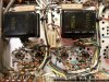
1. One output stage with the old cathode (pin #3) and screen grid (pin #9) wiring cleared out.

2. Output stage work finished in both channels. As can be seen, the old damping circuit components are gone, the Phase Reverse switch wiring has been restored, screen stability resistors have been added as have individual 10 ohm cathode resistors to each output tube, and the cathode terminals can now be accessed by the C and X terminals on the output terminal strip. The goal was to make these modifications, without drawing undo attention to their installation. In other words, make it look as stock as possible. By in large, I think that goal has been achieved.

Next up, the new power switch has arrive and been installed on the volume control/loudness switch assembly, so that needs to be reinstalled and connected, and one other pair of coupling caps needs to be changed out. Then it will be time to power this puppy up, set the chassis controls, as see just what the heck I've got!

Dave
 

Attachments

  • Finished X-202 Output stages 001.jpg
    Finished X-202 Output stages 001.jpg
    97.6 KB · Views: 138
  • Finished X-202 Output stages 002.jpg
    Finished X-202 Output stages 002.jpg
    110.1 KB · Views: 148
Last edited:
Volume Control/Loudness Switch Assembly

With the arrival of the new power switch (which fit perfectly!), this assembly (with the loudness switch previously repaired), has now been reinstalled and reconnected into the circuit.

This is an area where detail is important, as there is much high level 60 Hz AC located in this area -- being with the low voltage DC supply bridge rectifier located in this area, as well of course as the AC power switch on the back of the control. The tubes located in this area operate at a signal level equivalent to the output of the line stage amplifiers, which is sensitive enough to pick up any stray 60 Hz energy if available, and reproduce it in the output as hum.

As a result, Fisher went to great lengths to contain this electrical energy, using shielded cable to supply power to the bridge rectifier, spring shielding over the AC power wiring, and a shielded cap over the back of the AC switch. Additionally, the cap is soldered to the back of the switch, and the switch is then soldered to the back of the volume control to help ensure these assemblies are well grounded.

All of these things must be in place, or hum will likely increase significantly. Therefore, I have tried to copy the original installation as much as possible -- not only to continue mimicking the stock build of the unit, but to minimize hum as well using the measures Fisher took.

So, other than the burned up shielded cable from previous repair efforts, the control should look much as it did when it left the factory.

With a little luck, I should hopefully have the 202B on the bench tonight!

Dave
 

Attachments

  • X-202 Reinstalled Volume Control 001.jpg
    X-202 Reinstalled Volume Control 001.jpg
    93.2 KB · Views: 100
WOW again! I wondered why they went to such trouble with all the shielded wiring harnesses in this amp.
 
Resuscitated!

A little love goes a long way, doesn't it?

Rebuilding the B+ and low voltage power supplies, rebuilding the loudness switch and replacing the power switch, reinstalling the Phase Reverse and Remote Volume Control features, installing the right fuse and some good tubes as well as their shields and the right front panel jewels (thanks again, Don!), along with bending the chassis back in shape put this sold for parts only unit back in operation. Then completing removal of the damping circuits, adding individual cathode resistors with test points, and installing screen stability resistors makes this unit ready for service in the 21st century.

The eternal bane of the original X-202 design would have to be the use of 12AT7 tubes in the line amplifiers. Nice sounding tube, but so hard to find quiet ones. Designed as an RF tube, it is a frame grid design that preceded the same design used with the 6DJ8 family of tubes -- which is typically just as noisy. Still, I was able to find three quiet ones as well as tubes for the rest of the small signal positions. A decent set of Russian military tubes fill the output tube sockets, and have held a steady bias now for about 4 hours. An old Mullard tooling 5AR4 handles the high voltage chores.

Once appropriate tubes were found, the DC bias and balance controls all did their jobs well, with the tubes all set for 27 ma (3 ma lower than spec) -- this because my line voltage was pushing the B+ about 30 volts higher than spec, which is rather normal these days. Still, the heater voltage was less than 5% high, so no particular adjustments were made other than the lower quiescent current to keep the dissipation at spec. The test points on the rear of the unit made adjustment and followup tweaking easy, and is a common sense I modification I would recommend to all owners of these amplifiers.

This thing is so classically Fisher. It does what it does, so well. Even with the well worn front panel, there is no escaping that fact (thanks Frannie!). It is also commendably quiet for such a complex unit. As a side note, this unit has the same basic circuit layout as the EL34 based X-1000, yet this unit is much, much quieter in stock form than Audiodon's stock X-1000 could ever hoped to have been. In any event, all the controls work quietly, smoothly, and properly, including the rebuilt loudness switch. And thanks to Fisher's double loudness tap volume control, it tracks perfectly between the channels from nothing to everything. This was surely Fisher's top of the line unit in its day. When you simply look at it underneath and take it all in in total, it was an amazing accomplishment of manufacturing. I know of no facility that could build anything like it today.

For me, the sound it produces is not as rolled off as that which (again, for me) typically defines the Fisher sound of later units. It is therefore quite detailed and defined in the mid and high end ranges, and is quite dynamic and responsive over the entire range, but does lose the very lowest octave -- which it could be capable of dealing with, with the excellent OPTs it uses. The low end loss is due to the built in LF filters, while the more detailed mid and HF response is typical of the active tone control design used in this series. In some defense of the design however, the low end material that is being chopped was never even available back in the day this unit was designed.

What a nice addition to have as a representative one of Fisher's best, at a time when stereo was so young!

Pics include:

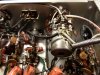
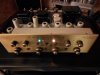
1. Operating for the first time in surely a long, long time.

2. Close up of the "distinguished" front panel. Heck, I even installed the new jewels in the sequence Fisher did.

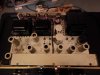
3. Top view in operation.

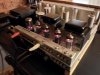
4. The tail end of business.

5. Along with some tubes and shields, it only took a handful of parts being replaced, others being rebuilt, cleaned, tightened, or straightened up, and some time, attention, and love to produce such a wonderful return on investment!

Dave
 

Attachments

  • Additional Finished X-202 001.jpg
    Additional Finished X-202 001.jpg
    45.7 KB · Views: 156
  • X-202 Operational! 004.jpg
    X-202 Operational! 004.jpg
    41.4 KB · Views: 152
  • X-202 Operational! 002.jpg
    X-202 Operational! 002.jpg
    55.4 KB · Views: 144
  • X-202 Operational! 003.jpg
    X-202 Operational! 003.jpg
    58.8 KB · Views: 147
  • Additional Finished X-202 002.jpg
    Additional Finished X-202 002.jpg
    88.2 KB · Views: 151
Dave,
This is coming together nicely and has been a worthwhile project.
It's looking pretty nice.

One thing I'm curious about.
EL-84s are an interesting tube.
Is this a 6BQ5 or a 7189 tube setup?

They often sound great. One thing I wonder is if they often sound great because they're low power tubes and therefore the surrounding circuitry is low power or if they have just enough power and that's part of their magic . . . big sound out of a small bottle.

What are your thoughts?
 
It's an interesting question Don. The EL84 family of tubes have a huge following both in the production and reproduction crowds.

Personally, I think much (but not all) of the following is emotionally driven. That's hardly to say it's not real. But rather, to say that the following is largely driven by empirical evidence rather than scientific fact.

Certainly the production amplifier crowd has more scientific weight on their side, as in guitar amplifiers, different output tube families do produce their own unique clipping characteristics at the onset of overdrive (which can be displayed on a spectrum analyzer), so the love from that group for this tube is more scientifically based.

In reproduction amplifiers however, those designs intentionally and inherently are supposed to eliminate such colorations as different tubes or distortion characteristics might present, so that a 6L6 amplifier, a 6550 amplifier, and an EL84 amplifier should all in theory sound the same (all else being equal) with the exception of power output. And yet, we all have our preferences. Ultimately, at the bottom of it all, is the fact that our preferences are largely emotionally based, because let's face it, great amplifiers can be (and have been) built with all of these tubes. In the end, they can all produce very low distortion levels for the power they are capable of, and yet the preferences exist, which begs the question then that you pose: Is it the tubes themselves that sound different? Or, the amount of support circuitry (or lack of it) that each requires that (potentially) flavors the sound?

Certainly the bigger tubes (usually) take more support circuitry and larger power supplies, while the smaller tubes take less of everything. No doubt that is part of the perceived difference in sound that each tube produces.

I have designed many amplifiers using 2A3, 6V6, 6BQ5, 7591, 6L6, EL34, and 6550 tubes in SE, PP, triode, pentode, UL, and PPP configurations, operating in Class A, Class AB1, and Class AB2. By in large, within their design topology and power limits, they all sound about 95% the same -- which they darn well ought to if they are all achieving a high level of distortion, response, and output impedance performance. But that other all important 5% is what makes or breaks our preferences. Sometimes, it's supported with "facts" that can't be proven, or on whacked out theories that have (and could only) grown legs on the Internet, but ultimately, always on our own subjective -- and very real -- sonic impression that we all have. Just look how much Sony has been able to achieve in that last 5% with tube and component rolling.

I think in the end you nailed it with your big sound out of a small bottle description. The tubes are capable of very credible performance that can be scientifically demonstrated and is repeatable, but also have a likability factor that blows that remaining 5% out the top of the equation. That's about the best I can make of it, as I must admit, I am one of those who does appreciate a good EL84 based amplifier.

As for the X-202, it specifies 7189 tubes, but really, any EL84 family member will work just fine in these amplifiers. The 7189 specification was largely driven by Avery's want to be the first to use everything first, and that tube came out as this amplifier was on the drawing boards, so it got the nod.

People look at tube specifications as gospel, and to a large degree, they should. But they aren't absolute. A tube with a plate voltage rating of 300 volts certainly won't blow up with 310 volts applied to it, if the important ratings are adhered to, and otherwise good design practice is followed.

As a case in point, my SA-100 clone amplifier (with EFB) effectively applies 430 volts to the plates and 315 volts to the screens of the Gold Lion EL84 reissue tubes I installed in that amplifier when it was finished. Both of these voltage values exceed the 300 volt maximum limits published for these elements of these tubes. The tubes were new when installed, and have now just surpassed 1500 hours of use in that amplifier. Before they were installed, they were each tested for power output and recorded. Last month, when the 1500 hour mark was reached, the tubes were removed and tested again. All were still producing at least 96% of their new recorded power output level. Yet -- these tubes are operating beyond published voltage specs -- and yet, have clearly done just fine in spite of it. As a matter of fact, the paint and getter flash on these tubes has yet to show any real signs of aging at all!

Dave

 

Attachments

  • EL84 Output Tubes -- 1500 Hours 001.jpg
    EL84 Output Tubes -- 1500 Hours 001.jpg
    41.5 KB · Views: 91
  • EL84 Output Tubes -- 1500 Hours 002.jpg
    EL84 Output Tubes -- 1500 Hours 002.jpg
    58 KB · Views: 99
Dave, this amp is truly a Phoenix rising from the ashes - great work!

I totally understand the emotional aspect of 'tube sound'. My first piece of gear when a teenager in the 60s was EL84s Dynaco ST-35 and PAS pre. It must have encoded my brain for I love the EL84 sound - it is just so sweet to my ears. I do enjoy the power from the bigger tubes but find myself coming back to that EL84 sound.
 
And there ya go. Even that "first impression" can make up (or help to make up) that 5% that determines our preferences.

Thanks for the kind words!

Dave
 
One thing I keep meaning to add, concerns the front panel "Rumble" and "Scratch" filter switches on the X-202.

These names imply that these switches only operate with and impact sound produced from phono inputs, since the terms rumble and scratch are descriptors associated with producing sound from playing records.

In the design of the 202 however, these switches are really the electronic origin of what became known on so many later units as "Low Filter" and High Filter" -- be it receiver or straight amplifier oriented. Specifically, I don't know of any design predating the 202, that includes such filters, designed into the circuit in the manner that they are in the 202.

The X-101ST certainly predates the 202 (being the first stereo integrated amplifier Fisher produced that I am aware of), and does include a Rumble Filter switch. But that switch in that design is decidedly connected to and operates only with the phono preamp circuits. In the X-202, the Rumble and (new) Scratch filter switches operate (for the first time) in the line amplifier stages, meaning that in spite of their designated titles, their operation actually affects the sound from any and all inputs.

It is strange then that Fisher would give these switches the designators they did on the X-202. But these were fast changing times during the early stereo days of 1960. The electronic aspect of how these filters function was certainly changing, but the descriptors they were given apparently lagged behind their changing operation. The X-202 went through all of its own iterations with these switches always labeled as Scratch and Rumble. Only with the introduction of the X-202B did these (basically electronically identical) filter functions finally become known as the more generic Low and High filter switches.

In any event, for those who have these amplifiers, just be aware that these switches will in fact affect the sound on all inputs playing through the X-202, so make sure they are set according to your preferences!

Dave
 
Looks great. I agree with your summation on the filter switches. On mine, the scratch filter seems to work regardless of volume but the rumble filter doesn't seem to make much difference until the volume is up around 4. With the Loudness Contour on, each filter takes on even different characteristics. By 4 or 5 on the volume control, the Contour seems to be completely overridden, the scratch filter makes less of a difference but the rumble filter becomes very noticeable.

There is a difference between this and the 500B. To me, the 500B is more mellow where the 202 is crisp and a bit more lively. Maybe it's because I have a few more miles on the 500 than the freshly recapped 202...
 
Excellent write up & review of the Fisher X-202. Your posts are the most educational I ever read. Thanks.
 
Hiya,

Dave thank you again for an informative write-up and rescuing this rascal from oblivion.

As to tubes sounding one way or the other. The best sounding amplifier I have ever heard was a PP 6AQ5 VM thing. The OPT's in it did not even look like they could but they did. (If you catch my meaning)

Honestly I think sometimes when a designer is faced with limited watts to deal with they tend to focus better. Higher wattage in my world usually indicates waste and sloppiness.

This tube discussion while meritorious might be better served being moved to its own thread. I just like looking at this survivor and will come back to this thread in the future when I tackle my own beat-up X-202 survivor.

Frannie
 
Back
Top Bottom