• The move to the new server is done. There are some software and database maintenance updates in process. This has us passing the hat around to help out. We appreciate any donations. Seriously, even a dollar helps. The payment page may be found here - https://www.audiokarma.org/support.html

Pitiful X-202

Yes, there is only one tube in the X-202 called a "TONE CONTROL AMP Ch A & B" which is V6. You will recall that the 12ax7 is a DUAL TRIODE and is therefor really 2 tubes in one. So it's doing double duty. V4 and V5 also are Tone control (in a strict sense of the words) as they are for the "Scratch Filter" or what we now call the HI-FILTER". The X-202 is kindof in a field by itself as most FISHER tube amps and receivers have the "TONE CONTROL AMPS split among 2 tubes vs 1 tube in the 202. And most of those other units have multiple roles for all of those tubes so they don't go to waste.
 
The filter should NOT be affecting the sound when it is in the off position. The best way to hear what it does is to put on a record and play it. Crank the Treble 2-3 marks with the Filter off. Now just turn on the HI-Filter and do nothing else. The high's above I think it's 10kHz are attenuated somewhat. Now turn off the filter and the high's come back. Originally it was called Scratch filter to take out some of the scratchiness and pop noise in the higher ranges on Records. Rumble Filter (now Low Filter) did the sam for anything from 100Hz to 250Hz or 500Hz depending on the make and model.

I
 
The HF filter is generally pretty benign when in the off position, but the tube associated with that filter is always active, amplifying on all sources. As I have posed before, remember that on the X-202 version that labeled these switches as "Scratch" and "Rumble", that these switches affect ALL inputs, both high level and low level -- not just the phono inputs.

Dave
 
Thanks Dave... I'm going to swap out the tone control tube and see if it makes a difference. I have used the 5751 in my 500B is it OK to use it in the X202 being that it's one tube for both channels?
 
I know that use of the 5751 tube in place of conventional 12AX7 tubes is a popular swap. In many pieces of Fisher equipment however, its use can really alter the intended operating parameters for whatever stage it is installed in -- and others as well:

1. As is generally understood, the 5751 only produces about 70% of the gain that a 12AX7 does. In stages that depend heavily on NFB to produce the correct response, this reduced "open loop" gain will then change the intended response the NFB is designed to produce. Most notably, use of this tube in the phono preamp positions will notably alter the LF response characteristics of the intended RIAA response curve (reducing bass response). In units with active tone control circuits (400C/CX/CX-2, X-202/B, X-1000, and 202T), use of the 5751 in the tone control position will reduce flat response, and the maximum boost/cut range available from these controls. In units with passive tone control circuits (all stereo receivers and lower tier integrated amplifiers), the greatest effect from using this tube in the tone control/filter position is a reduction in input sensitivity, along with slightly reduced filter effectiveness.

2. The other virtually never addressed concern for using this tube, is that the heater of the 5751 draws nearly 17% more current than the heater of the 12AX7 does. This then has two other impacts on Fisher gear:

A. If all the phono preamp, filter and tone control 12AX7 tubes are replaced with 5751 tubes, then there is now 17% more current being drawn from the DC heater/bias supply for those units using this topology (all FM Stereo MPX receivers, preamps, and top tier integrated amplifiers), with the result being that the heater voltage to the series tube circuits is now reduced by over a volt, and output stage current draw is notably increased. For lower tiered integrated amplifiers that power the heaters of these stages by way of direct output stage current draw, current flow through through the output stage is notably increased as well with the use of 5751 tubes, because of the change in bias voltage they produce. Of course, the increased current draw has a direct impact on the heat produced by the power supply components, which now needs to supply this increased current on a continuous basis.

B. Because Fisher equipment invariably uses heater string configurations to power the heaters of the tubes used in the stages being discussed, use of an odd lot of 5751 tubes can produce different types of unintended consequences. For example, the popular notion of using these tubes in the phono preamp position by themselves not only leaves them starved for heater voltage, but also then potentially over-voltages the heaters of other 12AX7 (or 12AT7) tubes that these 5751 tubes are in series with (in some units), leading to a notably shortened life for those tubes. Depending on the way the heater strings are wired, the use of an odd lot number of these tubes will then alter the sound of either one or both channels, and in unexpected/unanticipated ways.

I hardly wish to dump on the fun of tube rolling. But if anything, this shows how the sonic "goodness" assigned to some tubes in reality is primarily the result of their interaction with the circuit they are installed in, rather than coming from some intrinsic quality they possess over more common types. Besides basic make up and characteristics, there can be differences between various tube types to be sure, such as in consistency of characteristics, tendency (or not) towards microphony, linearity, etc. But in high fidelity equipment, the greatest sonic impact from the use of one tube type over another will primarily be due to the interaction that the tube has with the circuit at hand, as the above example shows. Therefore, when you casually change between tube types in your tube rolling exercises, just be sure the account for the collateral issues that such changes can make.

Dave

 
Last edited:
I'll stay away from the 5751. I have a Sovtek new issue 12AX7 in it right now. I'm going to try the Telly 12AX7 I have.
Thank You for your knowledge.
 
3. To complete the work, 100 ohm 1/4 watt Screen Stability resistors were added. The original design of the X-202 was not particularly known (to my knowledge) to cause premature output tube failure (arcing). But with the replacement of the existing filter caps with modern electrolytic caps that have lower ESR values, and as a possible prelude to installing EFB, the Screen Stability resistors were added as a safety factor, and because it just makes so much sense to do so while I'm in there.

do these have to be 1/4 watt, or is 1/2 watt also OK for these Screen Stability resistors?

also, do they need any particular voltage rating?

thanks
 
Either wattage rating will work, but the use of 1/4 watt units will help them to better act as a fusing element as well, while still allowing sustained full power output to be developed without concern for resistor heating. The voltage rating is unimportant as there is only a couple of volts dropped across these resistors, and that is only as full power output is reached. Keeping the leads to these resistors short allows them to provide maximum effectiveness against high energy parasitic oscillations.

Dave
 
thanks Dave!

I'm restoring a Fisher X-202, and working on the output tubes area... will be making the "Individual Tube Bias" mod, plus the "Screen Stability Resistors" mod

I have a question about the RESISTORS in this area... most are reading somewhat high, with a couple a little bit out of spec

I want to replace ALL of them to make sure everything is in good order, robust, and reliable for the long term... I've also had an issue with some weird bias readings on one tube socket position, so want to rule out the resistors

have been reading up about the pros/cons of the various resistor types: carbon comp, carbon film, and metal film, and getting really confused!... metal films seem great (very precise, stable and cheap), but according to some it seems that carbon comps "have" to be used in certain areas, eg. plate load resistors and grid stoppers (and to be honest, I think I can identify these, but I'm no expert by any means)

I want to preserve my vintage warm tube sound for sure, but also want reliability and long life

I'm tempted to just put in all metal films, or, all carbon comps, because I'm not knowledgeable enough to figure out what to put in where... my parts vendor does not seem to carry carbon films in the regular sizes, so hopefully can avoid those)

can you please suggest the best approach?

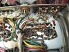
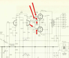
I've attached a photo of the resistors in question for one representative channel only... there are 6 resistors in total:
R123/126 = 2.2K
R117/119 = 220K
R 124/125 = 47K

(of course, I will be removing R134 and replacing with a pair of separate 10 ohm 1% metal films for biasing)
 

Attachments

  • DSCF0210.JPG
    DSCF0210.JPG
    133.7 KB · Views: 33
  • output_tube_area.png
    output_tube_area.png
    437.5 KB · Views: 30
None of the resistors you've cited are crucially important with regards to precise value. That's because they all work together with the three Bias and Balance controls that serve each channel. All that their replacement with precision units will do is maybe cause a slightly different setting of these controls from where they would optimally be set with the current components installed. Even more importantly, there will be far greater circuit impact by the slight differences in individual tube characteristics for the tubes used, since they are active components, where as the resistors are passive components. In a nutshell, that's why the controls exist in the first place. It will be a tremendous amount of work to replace all of the resistors, that will return you little for all the work required. Now, there are resistors where hi precision is of value, such as the individual cathode resistors, and more generally, any resistors that are part of the various NFB networks used throughout the amplifier. Beyond that however, the use of precision metal film resistors will serve mainly to ensure the lowest possible noise from the unit -- although Fisher already did a very good job of selecting low noise resistors to produce the unit in the first place. So even on that front, the return will be very small. The exercise may produce a high emotional return, which is hardly a bad thing. But in terms of tangible returns, replacing all resistors with metal film won't produce any significant operational differences from that produced by the original build.

I would first install the individual cathode resistors, and possibly convert the rear panel damping terminals to test points (as recently explained in a separate thread), and recap all the electrolytic and film caps throughout the unit. Then, see where the unit stands operationally relative to further component replacement. It may just be a whole lot better than you might think.

Dave
 
None of the resistors you've cited are crucially important with regards to precise value. That's because they all work together with the three Bias and Balance controls that serve each channel. All that their replacement with precision units will do is maybe cause a slightly different setting of these controls from where they would optimally be set with the current components installed. Even more importantly, there will be far greater circuit impact by the slight differences in individual tube characteristics for the tubes used, since they are active components, where as the resistors are passive components. In a nutshell, that's why the controls exist in the first place
thanks Dave

I had a thought regarding the resistor type used in conjunction with the output tubes

since these resistors (in conjunction with the adjustable pots) control critical aspects of the tubes, ie., the DC balance between tubes in a pair, and the bias, wouldn't it be better to choose resistors that do not vary in value with temperature?... I've heard that the temperature coefficient for carbon comp resistors is very high, while being very low for metal film... since these resistors are in an area that will surely heat up as the amp warms up (right beside the output tubes), wouldn't it be better to use metal film for better stability of output tube parameter settings?

I'm not sure if the temperatures go high enough to make a difference, but one thing I have noticed with this amp is that it definitely sounds better after it gets fully warmed up, approx. after 1 hour of playing... something must be causing that, perhaps this is it???
 
and possibly convert the rear panel damping terminals to test points (as recently explained in a separate thread),

can you perhaps point me to that thread?

yes, I'd like to remove the damping circuit and free up those terminals to permit external bias setting... I guess the easiest thing is to simply clip the leads at the C and X terminals and cover the exposed wire ends, but I'd rather "rip it all out" correctly... do I just follow all wires back to the next junction and cut the wires there?

thanks
 
No doubt that metal film resistors are less sensitive to changes in value versus environmental temperature. From a standpoint of absolutes then, they will be better in that regard. Again, however, if you're changing the resistors you cite because they are damaged or well off in value, then no doubt using metal film is the way to go. On the other hand, if you're changing them in the search of some significant improvement in bias stability, I think you will be hard pressed to observe that end, as you're working in that "n"th degree realm of "in theory".... Hardly a bad way to go! I'm just trying to give you a reality of expectation. The X-202 I currently have here (that the thread I mentioned is based on) has very stable bias in operation covering several hours, using the original production components.

The thread regarding the test points can be found here: http://audiokarma.org/forums/index....bias-balance-test-points-to-the-x-202.733937/

Dave
 
No doubt that metal film resistors are less sensitive to changes in value versus environmental temperature. From a standpoint of absolutes then, they will be better in that regard. Again, however, if you're changing the resistors you cite because they are damaged or well off in value, then no doubt using metal film is the way to go. On the other hand, if you're changing them in the search of some significant improvement in bias stability, I think you will be hard pressed to observe that end, as you're working in that "n"th degree realm of "in theory".... Hardly a bad way to go! I'm just trying to give you a reality of expectation. The X-202 I currently have here (that the thread I mentioned is based on) has very stable bias in operation covering several hours, using the original production components.

The thread regarding the test points can be found here: http://audiokarma.org/forums/index....bias-balance-test-points-to-the-x-202.733937/

Dave
thanks Dave... that thread looks fantastic, just what I needed!
 
looks like I have a couple of cracks in two of my wires... see red arrows in attached photo

these are in the brown & green wires connecting to pins 2 & 3 on each output tube... these feed the tube heaters and are all connected together

the cracks are large enough that I can see the wire exposed a tiny bit, and a continuity check confirms this

also, these wires seem to be rather hard and stiff, I imagine because of being near the output tubes... and a bit of greenish oxidation on the exposed ends

Q: I suppose it's critical that these get replaced?... if so, what is the best wire to use?

I've only ever used braided "hookup wire" 18 AWG for most general purposes, but this seems to be solid core wire

should I use solid core, and what gage or other parameters are critical?

cracked_wires_2016-09-30_1150.png

thanks!
 
Those are the heater wires and are on pins 4&5 (not 2&3). Solid wire is nice to use, as it can be formed into position, and it will hold that position. Stranded wire will not hold a formed position nearly as well without significant work. If the tubes have run hot, then cracking is not uncommon. There's little danger if you don't replace them at this time, but if you do, 20 ga wire works well in this application.

Dave
 
Those are the heater wires and are on pins 4&5 (not 2&3). Solid wire is nice to use, as it can be formed into position, and it will hold that position. Stranded wire will not hold a formed position nearly as well without significant work. If the tubes have run hot, then cracking is not uncommon. There's little danger if you don't replace them at this time, but if you do, 20 ga wire works well in this application.

Dave
thanks!... and you're correct, they go to pins 4 & 5
 
I'm trying to understand what the big filter capacitors do, and if it's worthwhile to increase any of their values for "better performance" (as I often see done during restorations)... there are 3 big multi-cap cans in this unit: C43, C46, C55 and the stock values are:

C43-A > 1000 uF 30V
C43-B > 1000 uF 30V

C46-A > 40 uF 450V **
C46-B > 10 uF 450V
C46-C > 10 uF 450V
C46-D > 40 uF 450V

C55-A > 40 uF 450V
C55-B > 20 uF 450V
C55-C > 20 uF 450V
C55-D > 10 uF 450V

** this is the first cap being fed by the tube rectifier, and seems that increasing it could stress the rectifier(?), so I will leave that at 40 uF

note that my selenium rectifier has been replaced with a new silicon device

wondering if I should increase any and by how much, and which locations are the most important... any advice appreciated, thanks!
 
Last edited:
Back
Top Bottom