• The move to the new server is done. There are some software and database maintenance updates in process. This has us passing the hat around to help out. We appreciate any donations. Seriously, even a dollar helps. The payment page may be found here - https://www.audiokarma.org/support.html

Please help me repair my Marantz 2230!

check resistors ... r775 r774 in the right channel ...
with the unit unplugged from the wall check resistance of the resistors above ..
they should read 0.24 ohms .. your meter may say more like nearly 1 ohm .. this is no problem though as you can see if all 4 resistors look about the same resistance ...
 
ok ...
there is maybe a burn in the circuit board .. you may see it if you look closely ... break is in that area leading to the transistor with no power to collector (case)
 
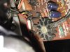
I removed the heat sink and pulled the board loose so I could do a better inspection on both sides of the board. There are no obvious burn spots anywhere that I can see, just some ugly spots where I have done some soldering.
 

Attachments

  • IMG_6977.JPG
    IMG_6977.JPG
    71.6 KB · Views: 59
That happened when I replaced that capacitor, I exposed the copper trace and made the leg longer than normal so it would reach. It appears to be a good solder joint to me, though not as substantial as the others.
 
Make sure you are using the right kind of soldering iron for PC board work - preferably a temp controlled soldering station. You shouldn't be leaving behind significant black and brown spots after soldering. That probably means too much heat and WILL lead to lifted traces and poor connections. And if you are having trouble getting a good solder joint after 3 or 4 seconds, stop, clean the area with isopropyl alcohol and apply a tiny dab of flux paste. It probably will solder easily. Too hot for too long will destroy a board. I'm telling you this as a noob who has learned the hard way. :D
 
Just for fun I switched the transistors around on the right side to see if it would make a difference. I still get correct reading on front one and 0 at rear. I'll try to test the driver transistors and resistors when I get off work.
 
The large transistor on the side of the heat sink and what I believe is the transistor driver?? both read the same thing

Fronts are 63.5v

Rear is 0v
 
the outputs are the large ones on the heat-sinks .
not familiar as to where the drivers are installed ..they are generally on the driver board
 
if you could get the voltages at
j756
j757
j758
j759
j761
we should get a better understanding of whats going on ...
 
Back
Top Bottom