• Please note that Audiokarma will be offline briefly for updates early on Monday morning, September 28th.

Point-to-point wiring

I just had a thought...maybe the ladies that were doing these point-to-point assemblies for the audio firms in the post-war years learned their trade making high-frequency stuff like vhf radios and radar systems during the war (and those kinds of circuit-path kinks can make a big difference in the black magic world of high-frequency)...

--Bob
 
Interesting post, Bob. Thanks.

The answer is right there in front of us. Gold/tin solder. :D I'm leaving the Al out as it's too hard to make it stick.

Murray
 
Bob E. said:
I just had a thought...maybe the ladies that were doing these point-to-point assemblies for the audio firms in the post-war years learned their trade making high-frequency stuff like vhf radios and radar systems during the war (and those kinds of circuit-path kinks can make a big difference in the black magic world of high-frequency)...

--Bob

This lady did assembly and test of RF cables. before the cables were argon welded they were backfilled with pure nitrogen.Yes the bends make a big difference. in so as certain freq. were very difficult to achive at the signal to noise ration.I talking about a cable that was sio2 with copper center. various conn. bnc tnc ect. I always thought that a solid cable would make the best interface for audio.
 
blue_lateral said:
There is a persistent story about Howard Vollum, founder of Tektronix. He was an electronics enginneer or tech of some kind in the military during WWII. The U.S. military required wires to be wrapped at that time, I believe two wraps on everything. Howard apparently felt very strongly that this was a bad idea. After the war, at Tektronix, he insisted that it not be done. There was some contention with the military about this, because Tek scopes were not "mil spec". Based on his experience during the war, Howard felt that if there was a bad solder joint, you wanted it to fall off so you could find it, rather than poke around for two days looking for it, possibly while under attack. There was also less chance of breaking stuff while doing repairs. He held his ground, and eventually the military saw it his way, or at the very least bought a bunch of Tektronix oscilloscopes.

John

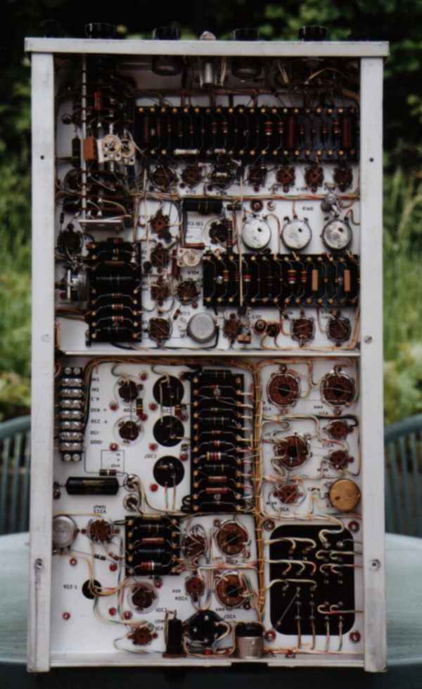
Interesting story, here's an example of some Tektronix work.
I took a look at this and it blew me away, each and every bend, angle and component placement look like it was well thought out beforehand - to me it looks like art. unbelievable!

Reminds me of Wardsweb's work as seen on his build pages.

tek1.jpg

tek.jpg
 
Celadon said:
Interesting story, here's an example of some Tektronix work.
I took a look at this and it blew me away, each and every bend, angle and component placement look like it was well thought out beforehand - to me it looks like art. unbelievable!

We've had lots of those come through the shop over the years....now, sadly, they get the tubes pulled and then scrapped. If you look around on the frame, near the top, you might find a small roll of solder popped onto a plastic nub...it's a special silver-bearing solder that Tek wanted you to use if you de-soldered and then soldered any components into those ceramic terminal boards. Ordinary solder would apparently loosen the plated-on solder pads over time.

--Bob

Additional: That picture sure illustrates Blue Lateral's point about Tek not wrapping their component leads...they are just laid into the slots of those terminal boards and the solder flowed in on top!
 
Celadon said:
Interesting story, here's an example of some Tektronix work.
I took a look at this and it blew me away, each and every bend, angle and component placement look like it was well thought out beforehand - to me it looks like art. unbelievable!
To me, it looks like a pipefitter laid it out!

(Full Disclosure: In my former life, I was a plumber.)
 
thats funny being thats the way basic electronics is described like a plumbers pressure vs flow thing? guess they took the same mechanical specs to match the electrical layouts.

Sure is easy on the eyes after 12 hrs looking at a assembly line ? :tears:
 
ozmoid said:
Actually, it's not a mess, it's a very neat job. The masses of solder are occurring where lots of wires attach at a single point (by "lots" I mean three or more) and all those wire loops are filled, making a big dollop of solder. I'm used to PCB soldering, where everything is either surface attached or pinned thru the board with just a speck of solder. I can see how the P-to-P technique makes assembly easier (I did the same thing putting it all back), but it makes disassembly a little more labor intensive. Thanks for the tip on the pick, I'll look for one!
Radio shack has a vacuum desoldering tool that works fine and dont cost much, i use mine to change horizontal output transformers , and use the braid for the smaller jobs.
 
Soldering on the ceramic strips can be interesting. My 535 had a working, but really kludged up high voltage section. I couldn't leave it like that. The soldering was awful on this old repair, and the ceramic strips were ruined. I think I can solder pretty good, but trying to hold things to the standard they were built to at Tek in the 50's was a little challenging. It was also fun.

I expected the ceramic strips would be tough to get hot. The opposite is true. The ceramic is apparently an excellent insulator of heat. The silver heats up extremely fast. I found the way to do it is to heat the crap out of the component lead. It is the hardest to get hot. Even a little flux will heat up the ceramic, way before the component lead is hot. I used the required silver bearing solder on the new strips.

Here is a before and after of the high voltage power supply:

hv_bef2.jpg

hv_aft5.jpg
 
They're 5642 diodes. The three on the right are a high voltage tripler that supplies +8650v to the CRT anode. The second from the left supplies the -1350v to the CRT cathode, and is also tapped for focus voltage. The one on the left supplies -1450v to the CRT control grid.

John
 
mhardy6647 said:
umm... I am lazy and I usually make "pigtails" from the cut leads of old components.
There's a nominal risk of forming an antenna for RFI, but I haven't had any noise/hash problems. E.g., the Marantz 8B I "restored" was so dead quiet, it was impressive.

Marantz8Bafter.jpg


EDIT: Adapting the little Hexfreds into the HV power supply was a little tricky!

Before:
P6060008.jpg


After:
P7090039.jpg

Mark pretty nice work. Please take the following with a grain. I have to ask why would you opt to use such a bargain bin cap in a work of art like the Marantz 8B? I think if you listened with a open mind to one with some higher quaility audio caps you maybe surprised. No I'm not advocating spending $30 a cap here but many options exist that are reasonable and will sound better in the amp. You only do the work once why skimp?

Craig
 
Same reason I used the Illinois caps :-) The amp's owner (who was reluctant to sling his own solder) bought the VTV rebuild kit. It is "just" the bias supply, after all!

I was just the hired gun! Heck, I gladly did the job gratis, for fun and for the chance to get to play with an 8B while I "checked it out". It is a marvelous sounding amplifier; best I've heard on my Cornies with my own ears, even with cheap-jack Sovtek EL34's that we had in there as "cannon fodder" in case anything went awry.
 
"It is "just" the bias supply, after all!"


Those yellow things sure look like IC caps to me and they are in the signal path at every curve turn and straight away.

VTV kit makes it easy to understand pay top dollar for low dollar parts.
 
The Illinois caps are of course in the signal path... I was referring to the cheapy electrolytics that you had originally called out, which are filters for the bias supply (NOT for the HV supply).

Actually, the VTV documentation was atrocious! Fortunately, I had a schematic and knew what I was doing. I wouldn't have advised anyone to buy the VTV kits before I actually saw one -- I would actively discourage anyone from buying one now that I've seen one (two, actually).
 
Back
Top Bottom