• The move to the new server is done. There are some software and database maintenance updates in process. This has us passing the hat around to help out. We appreciate any donations. Seriously, even a dollar helps. The payment page may be found here - https://www.audiokarma.org/support.html

Power supply ringing

kward

AK Subscriber
Subscriber
Is anyone else concerned about power supply ringing? I don't know if this really matters, but it's something I am more cognizant of these days. Power supply ringing can happen when a power amp attempts to reproduce a low frequency transient and the power supply is not regulated. May not be that big of a deal in line level or preamp type gear because the current swings are much less. But in a power amp, seems to me that because of the larger change in current demand from the output stage when reproducing low frequency transients, the power supply could have a tendency to ring as it adjusts to delivering the current needed. Seems to me the size of the power supply caps, especially low ESR caps, can affect the duration and damping of the ring as well as any series resistance in the supply itself (such as purposefully placed dropping resistors or DC resistance of chokes). So it may not always be better to use larger caps in the power supply unless this aspect is dealt with.

But...power supply ring is a new area for me that I am starting to explore. Anybody have experience here? Is this a legitimate concern?
 
Register to hide this ad
How much ring is tolerable? I assume you want the frequency of that ring to be lower than the amp can reproduce and that you want to damp it out as quickly as you can, say one cycle.
 
I don't think it's possible to specify how much ringing is tolerable in isolation. It depends on amplifier PSRR and load transient magnitude.
 
Is anyone else concerned about power supply ringing? I don't know if this really matters, but it's something I am more cognizant of these days. Power supply ringing can happen when a power amp attempts to reproduce a low frequency transient and the power supply is not regulated. May not be that big of a deal in line level or preamp type gear because the current swings are much less. But in a power amp, seems to me that because of the larger change in current demand from the output stage when reproducing low frequency transients, the power supply could have a tendency to ring as it adjusts to delivering the current needed. Seems to me the size of the power supply caps, especially low ESR caps, can affect the duration and damping of the ring as well as any series resistance in the supply itself (such as purposefully placed dropping resistors or DC resistance of chokes). So it may not always be better to use larger caps in the power supply unless this aspect is dealt with.

But...power supply ring is a new area for me that I am starting to explore. Anybody have experience here? Is this a legitimate concern?

This is a valid concern. If your are serious about this problem, then use of active regulation will help a lot, though for the price of heating the air.
 
How much ring is tolerable? I assume you want the frequency of that ring to be lower than the amp can reproduce and that you want to damp it out as quickly as you can, say one cycle.
Hi KW, your question is a serious issue with diy'ers who are frequently using components such as chokes and power transformers that they have on hand. I just stay over the minimum inductor limit and hope that the recycled transformers don't have any issues. Sometimes they do and you just need to put another one in. But, how to dampen ringing, without going to SS devices, that would be an excellent issue to discuss. It would be great if someone who knows how to do that would chime in.
 
Ringing in any L/C circuit is a function of Q, which is simply the ratio of reactance to resistance. Q is sucked out by the power supply's normal load resistance, just like the termination resistance of any L/C low-pass filter, as well as the non-ideal characteristics of its chokes and capacitors. It's worth noting that constant-current loads behave like very large resistances and therefore offer little power supply damping. Film caps can exacerbate ringing because of their low D (dissipation factor) relative to electrolytics. It's possible to damp out ringing by adding resistance here and there, but chokes are persona non grata in my own creations. Two R/C filter sections using modern high-capacitance electrolytics easily outperform an L/C section in every way, including loss of regulation due to series resistance, and R/C sections are impervious to ringing.
 
As just nicely outlined by BinaryMike, a power supply typically doesn't show much resonant behaviour, even though a quick visual of a schematic with LCLC etc filtering may cause concern. PSUD2, when appropriately set up, will likely show that even filters with LC sections, will have well damped step load responses, due to the practical winding resistances of chokes, and the normal amp loading.

I guess the caveat to that is some form of motorboating, or unmanaged amplifier gain at very low frequency, which is close to the power supply damped frequency response, and somewhat in phase. The influence on any amp would likely just be to the output stage, as upstream stages would be likely well isolated by typical power distribution filtering. The influence on B+ should also be viewed from the perspective of the mains harmonic ripple magnitude that is pre-existing (but usually attenuated in the output signal to an adequate extent).
 
Very helpful and informative responses. Thank you.

Two R/C filter sections using modern high-capacitance electrolytics easily outperform an L/C section in every way, including loss of regulation due to series resistance, and R/C sections are impervious to ringing.
I guess it depends on the size of the electrolytics relative to the size of the choke. But I get the idea--that large electrolytics in a CRCRC configuration can do a lot of smoothing similarly to a small choke in CLC configuration and take up less room doing it.

PSUD2, when appropriately set up, will likely show that even filters with LC sections, will have well damped step load responses, due to the practical winding resistances of chokes, and the normal amp loading.
Yes, some sample circuits I ran did show quite high damping with a CLCRC type setup, where the B+ tap for the output stage was taken at the second cap. Ringing can be nearly entirely eliminated (according to the simulations) by adding a few ohms of resistance before the choke and setting the size of the cap after the choke appropriately (not too large, not too small). Down stream of that it didn't seem to matter at all one way or the other..
 
Last edited:
With the size of caps and chokes that are easily available these days- it's possible to put any ringing frequency SO low, that it's easily damped out.

I've modeled many, MANY power supply topologies before building them- and I've managed to get LCLCRC supplies to where they have no more than a few millivolts of LF ringing. And usually, it's at something like .01Hz. That isn't going to cause any trouble.

I am currently working on such a supply, to re-work the design on an amp in progress- using EL34s or possibly 6550s under low voltage (about 275v B+), to make about a 20w/ch amp using the Leslie 100-12 output transformers. It looks like it's going to work well- with the PT choices I have here, I was having a hard time finding that low of a voltage with enough current (the OPTs are 2K/4K, into 4 ohm/8 ohm respectively, so they need current, not voltage, to drive them), and the LCLC choke-input filter seems to have solved that problem...

Regards,
Gordon.
 
Interestingly if you implement a regulator incorrectly, those can ring or "hunt" well within the audio band. Most of them want a cap right at the output to quench this, and if that goes bad or isn't used the output tends to make a sort of pumping noise as the output voltage changes.
 
Oh, one thing I didn't mention- it's helpful, to avoid ringing, to make sure that in an LCLC supply, that the chokes are very different in value, and that the resonant frequencies of the LC sections differ greatly from each other as a result. In my LCLC filter mentioned just above, the first inductor is 3H, and the second is 0.6H (600mH). That's a difference of 5x- and also, one is not a multiple of two, of the other- and that's a large factor toward it working as well as it does.

Regards,
Gordon.
 
The stepped load, in PSUD2, can teach you a lot about this. One thing which I learned by playing with this function, is that the dynamic performance of power supplies is VERY different, depending on their topology, even when the static performance appears similar. With a single ended amplifier, this is really relevant, and helps explain why single ended guys fuss so much over power supplies. (push-pull is way more immune to power supply issues)

There is no free lunch, you're weighing ripple, against recovery time, and ringing versus recovery time too. Any sort of power supply is going to be audible, since it's a complex impedance in series with the output transformer.
 
Ratio of input to output capacitors also affects filter Q - larger output capacitors are best. As mentioned, look at the stepped load results in PSUD.
 
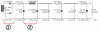
I've been studying this topic in more detail over the past week. I now see that ringing could occur whenever you have an LC circuit. In the diagram below of a typical power supply used for a tube amp, I believe there are two opportunities for ringing, labeled 1 and 2.
upload_2017-1-29_19-46-4.png

Considering case (2) first: stepping the current load of I1 in PSUD, or just watching the initial rise of the voltage on C2, I was able to see the ring in simulation caused by this CLC circuit. I realized however, that I might be missing a resonant circuit at (1). This resonance is created by the leakage inductance between primary and secondary windings of the power transformer, along with the winding capacitance (thus another LC circuit, although not obvious at first glance). When current abruptly stops flowing due to the diodes switching off (as part of the rectification process), the circuit rings. It is my belief that these two sources of ringing are audible, at least to some extent.

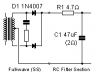
The apparent typical solution to damp both sources of ringing is to fit in "snubber" circuits. In case (1), the snubber consists of a cap in series with a resistor hung directly across the secondary winding (usually about 0.1 uF + 50 ohms or so, but depends on the transformer). Like so:
upload_2017-1-29_21-5-20.png

Some solutions fit in a second "snubber" capacitor in parallel to the added C+R shown above to swamp out the internal winding capacitance. In any case, the purpose of the snubber is to absorb and release energy in semi-opposite phase to damp the ring.

In case (2), the snubber consists of two back-to-back capacitors (typically .1 uF or so) hung one on each side of the choke and connected together on the other ends, and those two ends are connected to ground at the center tap, and where the snubbing resistance is the internal DC resistance of the choke itself.

In the first diagram above, the capacitors are not .1 uF--they are much larger at 47 uF and 200 uF, but in conjunction with the series resistance of the choke, and the value of R1 (4.7 ohms), as well as the series resistance of the secondary winding, I believe you can find values of R1, C1, and C2 that meet both the criteria for snubbing the ring, as well as offer sufficient capacitive loading for proper ripple rejection and current demand for the output stage of a power amp. (that's my supposition anyway).

So it is my belief that correctly addressing both sources of ringing should make a very clean power supply that responds well to both HF and LF transients, giving a very "clean" sounding power supply for tube audio circuits.

At this point, all of this is just theorizing on my part. Am I on the right track with this thinking? Set me straight if I've wandered off somewhere.

 
Mark Johnson over at DIYaudio has designed two automated transformer ringing detectors which allow snubbers to be developed: Quasimodo and Cheapomodo.

No math, no sliderule, no theory, just connect to the transformer then tweak as one watches the scope until the ringing vanishes. This is the way to eliminate ringing, instead of laboriously solving equations which tend to not work in practice.

Quasimodo is the fancy one (no kits left):

Cheapomodo is the latest incarnation. Not as fancy, but it should more than do the trick. Description:

Some Cheapomodo kits remain available for $13 delivered:
Disclaimer: I have no connection to MJ except as a highly satisfied customer. YMMV.
 
kward, could you elaborate on what snubber you are proposing for the main CLC filter please, as I interpret your description as just adding another 'C' across each C in the CLC filter.

The advantage of PSUD2 is to indicate the ringing frequency. The damping, and how much actual voltage perturbation occurs from a stepped loading, needs a little more effort to practically describe. The amp itself will determine what 'step load' occurs on a B+ rail (eg. idle no signal condition to the application of a high frequency, high amplitude signal) - well worth measuring first. Also, the perturbation needs to be looked at in comparison to the ripple voltage amplitude and frequency that is nominally on B+. If that then shows up a problem, then perhaps look for an answer.
 
@trobbins I'm not necessarily proposing a solution, but more asking if I'm going down the right path in my thinking. It isn't clear to me how to damp the ring in the CLC portion of the circuit, when the choke is in between two large filter caps. What I do know is what PSUD is telling me, which is that when you step the current at I1, the voltage as seen on the positive terminal of C2 does exhibit some damped ringing (at least that's what I'm calling it--ring--until I know better). PSUD indicates you can control the ring by adjusting size of C1, C2, and R1. What's confusing though, is this really a snubber for the choke? And is what I described (adjusting the sizes of C1, C2, R1) the best way to curb it? Or is it more proper to use whatever filter cap sizes you need on either side of the choke to get the ripple rejection you want, but then also add some smaller caps of say .1 uf each on either side as an actual snubber? But if you put two smaller 0.1 uF caps on either side of the choke, they will just add to the size of the filter caps already there, so they seem superfluous in this example. That's where I'm not sure what the right solution is. But I agree I haven't done all the effort to characterize this completely because I'm not sure if I'm even going down the right path yet. I guess I could do some more sims, or hook up an actual circuit and try it out that way to gain more insight.

Also, I realized in my previous post I may have drawn the snubber across the secondary of the power transformer incorrectly. Because it is full wave center tap rectified, I think there should be two R/C snubbers connected from each end of the secondary to the center tap. Anyway, it's the idea that I was trying to convey in my previous post, not actual working circuits.
 
There's an article by Morgan Jones in a recent issue of Linear Audio describing an extensive investigation of snubbing networks. Jones concludes by saying that a series network of 1K and 1nF across the secondary winding works about as well as anything, and makes commodity rectifier diodes perform as well as the boutique stuff. I don't recall that he suggested separate snubbing networks for center-tapped windings.

The current source has infinite resistance, so it's not a realistic load by itself. You might try paralleling it with a resistive load to simulate damping more like the real world.

Edit: The article appears in Linear Audio Volume 5 and is titled Rectifier Snubbing -- Background and Best Practices.
 
Last edited:
Back
Top Bottom