• The move to the new server is done. There are some software and database maintenance updates in process. This has us passing the hat around to help out. We appreciate any donations. Seriously, even a dollar helps. The payment page may be found here - https://www.audiokarma.org/support.html

Power supply ringing

If kward's sim circuit was used with a 500V rated electrolytic, then the ripple current in the first 47uF cap would get close to max rated for a Nichicon UCY. For that particular filter configuration (low first C, and moderate load current), there is good benefit in using series caps - for cost, ripple current, and voltage margin.

Agree 100%. I use this tool and set the all current taps stepped, with full conductance after 10 seconds like the real world and which is enough for simulation.
Then you can visualise the voltage the caps takes: well you'll see often you max or exceed the max rated voltage for a couple of seconds, which is not that dangerous but will certainly shorten the life of the cap.

I now always avoid that situation when I design/restore something.
 
Then you can visualise the voltage the caps takes: well you'll see often you max or exceed the max rated voltage for a couple of seconds, which is not that dangerous but will certainly shorten the life of the cap.

Yes, exactly so.

When I first discovered PSUD I plugged in some common power supply circuits I'd seen. Every last one of them momentarily exceeded the rated voltage. Given the nature of the application, tolerance for such overloads was likely built in to the capacitor specifications over and above the rated voltage limits.
 
I'm keenly interested in the ripple current topic, as well. I've read a tech note two on it from cap manufacturers, but it always seemed a little opaque to me.
 
and in the 40W EL84M amp I'm planning now, < 8Hz (60uF -> 2.5H -> 100uF).

Interestingly, after putting as much of the power supply as I could from this amp into PSUD last evening, it appeared perfectly damped when I stepped the load from idle to full power. Perhaps the extra resistance of the vacuum rectifier helps in this regard? (I'll post the PSUD file later.)
 
Interestingly, after putting as much of the power supply as I could from this amp into PSUD last evening, it appeared perfectly damped when I stepped the load from idle to full power. Perhaps the extra resistance of the vacuum rectifier helps in this regard? (I'll post the PSUD file later.)

What ESR did you specify for your capacitors? That, plus the resistance of the choke, helps damp the system. There's a lot of hidden resistance beyond the rectifier. A tube rectifier, for those of you not familiar with this, has variable resistance. As current increases, the voltage drop increases, and as current decreases the voltage drop similarly decreases.

"Perfectly damped" does not, alas, fully describe what you're seeing. Is there oscillation which rapidly stops, or no oscillation at all?

Damping comes in three varieties.
Under Damped (0 ≤ ζ < 1). Oscillates above and below zero at its natural frequency (w × d) where (w = 2 × Pi × f). Think saloon doors which swing back and forth until they gradually stop.

Critically Damped (ζ = 1). Most rapidly converges to zero any with no oscillation. Think of a door closer which perfectly closes door at the optimal rate so the door closes without a sound.

Over Damped (ζ > 1). Converges to zero any without oscillation, but takes longer than a critically damped system. Think of a door closer sized too small so door slams shut, but slower than if nothing were present.​
 
"Perfectly damped" does not, alas, fully describe what you're seeing. Is there oscillation which rapidly stops, or no oscillation at all?

None at all, that I could see. I'll double check again before I post the PSUD file.
 
I have to thank Kev, Kward, for helping me sort out my power supply for the amp on the left. I constructed it with a CLCLC filter of 12uf x 5H x 50uf x 5H x 200uf ( 2 x 100uf). I thought it would be a nice layout to have each ASC 100uf oil cap on each channel. As nice as that was, aesthetically, there was something off on the sound. To me it sounded a little like ringing, as the harmonics were exaggerated and the f and s sounds were somewhat highlighted. Lss, Kev, ran the PSUD sim for me and recommended that i add some capacitance to the C2. Without any other changes i tacked on another 50uf cap to the C2 upping its value to 100uf. This easily cured the skewed sonics. Although this removed the sonic oddities, it also had a negative effect. It made the sound seem slower and somewhat overdamped, lacking some of the dynamic force that the other filter had.
So, i downloaded PSUD2 and with the help of KW started playing with my power supply components. I found that going to 12uf C1 , 100uf C2 and 100uf C3 was better than my previous PS and just required some careful rewiring.
Now, that the ps has been corrected and i have the amp hooked up to the Altec 19 speakers, everything is peachy keen! The dynamics are back and no disconcerting sonic artifacts. Also i just discovered that the amp is quieter too. I guess the new layout reduced the amount of stray noise that was being put into the power supply. This amp finally sounds as good as it should and big big plus, i now can start using PSUD as another tool for helping to build better sounding amps.
Uno grande muchas gracias, senor Ward. adios mi amigo. Primo
 
Last edited:
This is great Primo.
What was PSUD2 showing with the first PS which was wrong and causing the issues you noticed with your hears?
 
This is great Primo.
What was PSUD2 showing with the first PS which was wrong and causing the issues you noticed with your hears?
Kevin, did that for me and for the life of me i could not get the sim to run with the original components. Anyway, according to Kev's findings there was nothing overtly bad about my ps, so that was reassuring. And he told me that adding more C to the C2 filter had better results, which was confirmed.
But, over the next days i learned more about using psud and got the sim to run with the rearranged componets of 12 x 100 x 100 uf. It seems that the values of the caps and their place in the filter were affecting the ps the most.
When i put the old ps arrangement in psud, i got an error message. I am a real novice at this so i am probably doing something wrong. So, i decided to go to the present arrangement and voile, tres magnifique.
The fact that the ps got quieter is confirmed by my meter measurement which now shows that at the power tube the residual AC is .024v and at the B+ to the driver tubes it is now .007 vac. and is confirmed by hardly any noise at the horn. This was not the case for the previous ps. where the residual ac was quite audible from 3 feet away at the horn level. Anyway, i am a happy clam and can now move on. cheers.
 
Muy Bueno, Kevin. can you run the same thing with 12 uf , 100 uf and 100uf and show the plot? gracias.
 
"Perfectly damped" does not, alas, fully describe what you're seeing. Is there oscillation which rapidly stops, or no oscillation at all?

Here's the PSUD file.

https://dl.dropboxusercontent.com/u/77169215/ST-40-Special.psu

I'll note that the 60uF cap before the choke is actually 2 120uF caps in series with balancing / bleeder resistors in my actual schematic -- but I can't specify that in PSUD. And the "I2" current tap is really the remaining load consumed by a regulated screen / front-end supply.
 
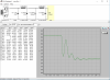
For Primo's PSU, changing to the values requested, gives this response.

1.jpg

This looks quite a bit better, but I think it can be better still with some more tweaking.
If you run the above at steady state at 120 mA current draw, the ripple at C2 is 158mV (peak to peak), and ripple on C3 is 0.5mV.

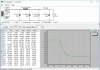
You might want to try some more tweaks to see if you can keep the ripple about the same, but get rid of that hump half way down the step. So just as an experiment, here's one tweak I tried:
2.jpg

This produces 40mV ripple on C2 and 1.1mV on C3 when run at steady state with 120 mA current draw.

Don't know if it will sound better though.
 
I'll note that the 60uF cap before the choke is actually 2 120uF caps in series with balancing / bleeder resistors in my actual schematic -- but I can't specify that in PSUD. And the "I2" current tap is really the remaining load consumed by a regulated screen / front-end supply.

Nice work. That looks really good. If I read it correctly, 60 mV of ripple at the output? Can't complain about that. The damping is not critically damped, which would be an optimal curve, but that doesn't matter.

If you are putting the capacitors in series the ESR should be additive. So that should be 4 Ω. It does not appear to make any significant difference by eyeballing the two, and I didn't expect it would. I looked up the ESR for C-D capacitors in that size and 2 Ω is spot on, even a little generous. The 2.5 H Hammond Choke also matches. S'all good.

In the real build did you add inrush limiters to keep the initial current spike down?

I also wonder if you can model ringing on your actual transformer that isn't showing up here. Have you considered trying either Quasimodo or Chapomodo to see what is going on there with the real device?

Can you imagine doing this in the old days with a slide rule or a hand-cranked calculator?
 
Nice work. That looks really good. If I read it correctly, 60 mV of ripple at the output? Can't complain about that. The damping is not critically damped, which would be an optimal curve, but that doesn't matter.

If you are putting the capacitors in series the ESR should be additive. So that should be 4 Ω. It does not appear to make any significant difference by eyeballing the two, and I didn't expect it would. I looked up the ESR for C-D capacitors in that size and 2 Ω is spot on, even a little generous. The 2.5 H Hammond Choke also matches. S'all good.

In the real build did you add inrush limiters to keep the initial current spike down?

I also wonder if you can model ringing on your actual transformer that isn't showing up here. Have you considered trying either Quasimodo or Chapomodo to see what is going on there with the real device?

Can you imagine doing this in the old days with a slide rule or a hand-cranked calculator?

Not a real build yet -- this one is just in the planning phase at the moment. I actually just acquired a CheapoModo that needs assembling, so once I get around to putting it together I can find the optimal snubber for the power transformer (lifted from a Heathkit AA-100).
 
For Primo's PSU, changing to the values requested, gives this response.

View attachment 862134

This looks quite a bit better, but I think it can be better still with some more tweaking.
If you run the above at steady state at 120 mA current draw, the ripple at C2 is 158mV (peak to peak), and ripple on C3 is 0.5mV.

You might want to try some more tweaks to see if you can keep the ripple about the same, but get rid of that hump half way down the step. So just as an experiment, here's one tweak I tried:
View attachment 862136

This produces 40mV ripple on C2 and 1.1mV on C3 when run at steady state with 120 mA current draw.

Don't know if it will sound better though.

Right, i can see that you added the 2 inductors together, and also the 2 caps. I can give this configuration a go and report back. The dynamics is excellent in the current configuration. Percussion is top notch hard to not start dancing along with David Bowie.
 
kward, some caution is probably needed when using a stepped current tap and looking at the shape of any resonant response, especially when there is no resistive loading on that node with the current tap. The extra LC end circuit (with only a light load on the C), means it will also ring in to the stepped current tap node.

What would have been great in PSUD2 would be a stepped resistor component model, as I'm pretty sure that would give a better representation of what the transient response would be.

If one was really keen, then a one-shot/capture oscilloscope measurement of the actual power supply voltage, using a switched amplitude high frequency audio signal would be the best cross-check, although a switched resistor loading may be close enough.
 
Right. I'm not sure how much one can trust simulation alone, and those supposedly nicer curves in simulation may not sound better on the actual build.
 
Back
Top Bottom