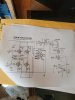
My suggestion for those unwilling to add flyback diodes or TVS diodes was to use a 470 Ω resistor.
This is pieced together from what I've previously written about placing a parallel resistor across the speaker terminals to avoid inductive kickback.
Why The Parallel Resistor
When the primary is pumped with energy the output transformer turns into an ignition coil. Somewhat simplified, because the transformer Secondary is unloaded the flux in the core gradually increases, but has no place to go. So the voltage climbs until current may flow, often as high as 2k V to 5k V, which then manifests as back EMF which then arcs in three places:
(1) Flashover arc between output transformer windings
(2) Flashover arc between the plate and other tube elements
(3) Flashover arc between the tube socket pins, usually plate to heater.
Four situations can cause this type of arcing:
(1) Running (signal input to amplifier) speakers which become disconnected
(2) Running (signal input to amplifier) without any speakers connected
(3) Running (no signal input to amplifier) speakers which become disconnected
(4) Running (no signal input to amplifier) without any speakers connected
Cases (1) and (2) obviously have a problem with energy being pumped into the Primary.
Cases (3) and (4) still have a problem because of (a) endogenous (amplifier-generated) noise and (b) the minor DC leaking into the Primary, which both pumps energy into the system and which, furthermore, may destabilize the feedback network, causing the amplifier to become unstable and pump more signal into the output transformer.
The result is the sound of a cash register, as you replace the output transformers and tubes. Even if the arc doesn't kill them the first time, it damages them and results in failure.
This is why large inductive loads, like DC relay coils and motors, use flyback diodes to dump the flux before it turns into high voltage kick and blows up the driving device.
Sizing the Parallel Resistor
The standard values for the resistor placed in parallel with the speaker are generally selected to be sufficiently high so as to:
(a) not significantly alter the overall load impedance, and thus not shift the load line (distortion)
—and—
(b) not significantly divert power away from the speaker (wastes amplifier output as heat)
but not so high as to cause amplifier instability. (More on this in a bit.)
TL/DR: The suggested value generally ranges from
220 to
470 Ω for speakers of
4 to
16 Ω.
Many ridiculous values, however, are bandied about on forums, apparently operating under the belief that current always flows through the lowest resistance in a circuit. That is a misunderstanding of physics and electrical engineering. For example, a lower value of
15 to
33 Ω is obviously unsuitable, as the overall impedance in parallel with
8 Ω would be approximately
5 Ω to
6.5 Ω. Even values of
100 Ω to
150 Ω, are unsuitable, as the impedance would be
7.41 to
7.59 Ω. Below set forth is the parallel resistance for various values to demonstrate the effects of various candidate values.
The reason the overall impedance matters is that an output transformer is an
impedance matching device, so the impedance at the Secondary creates a specific load at the Primary, depending upon the Primary::Secondary ratio. Every tube has a particular range for the output resistance which yields the lowest distortion, and the amplifier designer (if competent) selects an output transformer to match the higher-impedance seen by the tube (typical values are
5,000 to
8,000 Ω) with the lower-impedance (
4 to
16 Ω.) of the speaker. Stability may also be affected, and that is later discussed.
Consider the effect of paralleling various values:
680 Ω || 8 Ω = 7.91 Ω
470 Ω || 8 Ω = 7.87 Ω
220 Ω || 8 Ω = 7.72 Ω
150 Ω || 8 Ω = 7.59 Ω
100 Ω || 8 Ω = 7.41 Ω
33 Ω || 8 Ω = 6.44 Ω
15 Ω || 8 Ω = 5.22 Ω
The calculations for
16 Ω and
4 Ω are left as an exercise for the reader.
The practical difference between
680 Ω and
220 Ω is not, in practice, significant, particularly when consider that nominal speaker impedance is a fiction, particularly as the driver approaches resonance. So the change of
0.15 Ω is not significant being
1.875% ≈ 2%. But a change of
1.4 Ω in the speaker load is 18% and highly significant, and a change in
2.6 Ω is 33% and profound.
The obvious question arises: why not use
3,300 Ω to
4,700 Ω because that would yield a value of
7.99 Ω which
appears to be perfect. Alas, no, this is a very, very bad idea. The fault, dear Flyback Bleeder, likes not in our resistor but in its reflected impedance. As above explained, output transformer is an impedance-matching device, presenting the output tubes with the optimal impedance for the tube's load line, which reduces distortion (tube is most linear) and optimizes the output power. When the speaker is disconnected the load is radically changed from, say,
8 Ω to, using a hypothetical.
4,700 Ω, and the tube's output may become severely distorted. Depending upon the design of the feedback network, when attempting to correct this distortion the amplifier may become unstable and oscillate, resulting in damage.
Superior Solutions
My suggestion of the resistor was for those who prefer to not modify the amplifier, but a superior approach, and one I have elsewhere discussed, is to both:
(a) Modify the amplifier with
clamping diodes — engineering argot calls this a "clamping diode" but the amplifier vernacular labels it as a "protection diode" or "reverse diode" — reverse biased to the B+ supply, such that when the voltage at the primary climbs above the B+ supply the diode breaks down and conducts, thereby safely dissipating the energy. The diode must be rated for several kV as the inductive kickback may rapidly spike.
(b) Augment (a) with a solid-state Transient-Voltage-Suppression diode — aka
TVS diode, also known as a "
transil" or by the older name of "
thyrector") acting much like a zener, across the primary and from each winding to the center-tap so as to conduct at the appropriate threshold and safely dissipate the energy. See, for example:
(An MOV is
totally unsuitable as it has very limited number of cycles before it fails as a short. Each conduction burns a lower impedance path through the device. This is why the MOV must never be used in a socket strip. I've elsewhere posted links to safety cautions about the MOV and fires resulting from same.)
Many refuse to add such protection claiming, "
this could never happen because I always verifying speaker connections prior to turning on the amplifier". Uh-huh. Sure. Because "always" verifying a black swan event leads to abandoning such checks. That's just how humans behave, being very poor at always following procedures which are (a) not required (airplane or rocket pre-flight checks), (b) not written down, or (c) over-ruled by distractions. Humans may also not notice a wire has been pulled out, such as during vacuuming. This isn't an indictment of anyone, it's just a consequence of a simple fact: we're made out of meat and meat is a bad substrate for computation, and even worse for repetitive procedures, even when OCD is in play. I have seen so many statements about "
I think I blew up my amp because I engaged in an unusual action where I..." to think that black-swan events cannot ever happen, because they do. Far too often.
The other argument is, "
I don't want any sand in my amplifier." Uh, yeah, sure. Even when the device is
not in the signal path and prevents, under dire situations, the total destruction of expensive, and often highly difficult to source, output transformers, output tubes, and other portions of the amplifier?
For best results the TL/DR is add clamping diodes and potentially a TVS. For fastest and easiest results use a resistor, but this is not guaranteed to be the best solution.