killer1997
New Member
Hello and welcome.
I apologize in advance for my broken English, but it is not my native language.
Pioneer SA8800 came to my table and was supposed to have a "slight defect"
As I had already made such an amplifier before, I started to perform a basic check of the fuses and measurements to see if any of the output stage transistors were shorted to ground. I turned it on using the light bulb, but the light bulb was on continuously, which already indicated trouble. I started with the preamplifier, which had one transistor damaged. I replaced it, while checking the condition of the capacitors - most of them were in good shape, only the orange electrolytes with a value of 1-4.7uF had quite high ESR (10 ohms and above).
The preamplifier itself has come to life and works very well. The power supply and relay protection of the loudspeaker outputs without the power amplifier module are activated. The VU indicator also works. The problem lies in the power amplifier module. I took out the module and started checking all the transistors one by one. Much to my surprise, ALL of them were functional. Having experience with the previous example, I remembered that the amplifier running only on the control transistors (without any load in the form of speakers) worked connected to the oscilloscope, and the drive indicator also worked (only on the +/- 48V power supply pin 25,26 plus ground)
In this example, working with only control transistors is a very strange thing. Applying a sine signal to the output creates strange waveforms. It is impossible to start the amplifier with a pair of terminal transistors - immediately the bulb glows continuously and the amplifier does not even start.
It turns on on the control transistors themselves.
Since the transistor tester does not have to detect all defects, I decided to change all the transistors one by one in one channel to test. Until I came to a situation where I replaced all of them, and it still had no effect.
The 48V power supply is normal, I checked with an oscilloscope whether there are any distortions or fluctuations.
I also powered the module from another power supply and fed the signal directly to the board, completely bypassing the preamplifier.
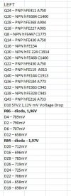
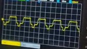
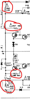
When I give a sine signal, e.g. 500Hz, the graph may look "optimistic" for a fraction of a second and then turn into something strange. I don't have a starting point that could cause an IDENTICAL fault in both channels. Comparing the boards with the previous copy, instead of resistors R84, 85, 86, 89 there are rectifier diodes (but this is rather a factory solution because the diode symbol is on the laminate)
I am also attaching stills from the video I recorded, showing what the process looks like after approximately half a second, one second, and two seconds.
I apologize in advance for my broken English, but it is not my native language.
Pioneer SA8800 came to my table and was supposed to have a "slight defect"
As I had already made such an amplifier before, I started to perform a basic check of the fuses and measurements to see if any of the output stage transistors were shorted to ground. I turned it on using the light bulb, but the light bulb was on continuously, which already indicated trouble. I started with the preamplifier, which had one transistor damaged. I replaced it, while checking the condition of the capacitors - most of them were in good shape, only the orange electrolytes with a value of 1-4.7uF had quite high ESR (10 ohms and above).
The preamplifier itself has come to life and works very well. The power supply and relay protection of the loudspeaker outputs without the power amplifier module are activated. The VU indicator also works. The problem lies in the power amplifier module. I took out the module and started checking all the transistors one by one. Much to my surprise, ALL of them were functional. Having experience with the previous example, I remembered that the amplifier running only on the control transistors (without any load in the form of speakers) worked connected to the oscilloscope, and the drive indicator also worked (only on the +/- 48V power supply pin 25,26 plus ground)
In this example, working with only control transistors is a very strange thing. Applying a sine signal to the output creates strange waveforms. It is impossible to start the amplifier with a pair of terminal transistors - immediately the bulb glows continuously and the amplifier does not even start.
It turns on on the control transistors themselves.
Since the transistor tester does not have to detect all defects, I decided to change all the transistors one by one in one channel to test. Until I came to a situation where I replaced all of them, and it still had no effect.
The 48V power supply is normal, I checked with an oscilloscope whether there are any distortions or fluctuations.
I also powered the module from another power supply and fed the signal directly to the board, completely bypassing the preamplifier.
When I give a sine signal, e.g. 500Hz, the graph may look "optimistic" for a fraction of a second and then turn into something strange. I don't have a starting point that could cause an IDENTICAL fault in both channels. Comparing the boards with the previous copy, instead of resistors R84, 85, 86, 89 there are rectifier diodes (but this is rather a factory solution because the diode symbol is on the laminate)
I am also attaching stills from the video I recorded, showing what the process looks like after approximately half a second, one second, and two seconds.