• The move to the new server is done. There are some software and database maintenance updates in process. This has us passing the hat around to help out. We appreciate any donations. Seriously, even a dollar helps. The payment page may be found here - https://www.audiokarma.org/support.html

Project: Marantz 1030

Comment: Don't do the full recap until you find and fix the problem with DC on the speaker terminals, otherwise when it doesn't work you will have a difficult time isolating the problem. o_O
I kind of figured that the problem would be gone when I recap (probably leaking capacitors?). They are all the originals and you can see leakage clearly.
I was going to start with the power supply board. Do you have other suggestions? Please do let me know :-) I'm new in the business.
 
See my updated post on the DC output capacitors. You should not have any DC at the speaker terminals.
 
I was going to start with the power supply board. Do you have other suggestions? Please do let me know :) I'm new in the business.
If the DC voltages coming out of the power supply are stable, then fix the DC speaker problem first, If there is a problem with the DC, then fix the power supply, then the DC output problem. Does the amplifier work now or recently?
 
If the DC voltages coming out of the power supply are stable, then fix the DC speaker problem first, If there is a problem with the DC, then fix the power supply, then the DC output problem. Does the amplifier work now or recently?
I actually just bought it. It does power on if that is what you mean.
The seller said it worked, so I hooked it up to some speakers and the moment I turned it on, I heard a "pop" in the speakers, so that's when I went to take my multimeter to get the voltage on the speaker terminals. When I power it on, you clearly see a voltage peak and then it becomes rather erratic (no stable numbers).

I tested the caps with my multimeter on the power supply board and none of them seem to be able to hold charge. I also see clear signs of leaking (the brown goo thing).
 
When I power it on, you clearly see a voltage peak and then it becomes rather erratic (no stable numbers).
When you first power it on, you may hear a slight pop as the capacitors are charging. Do you measure a DC voltage on the speaker terminals after power-on with the volume control turned all the way down?
I tested the caps with my multimeter on the power supply board and none of them seem to be able to hold charge. I also see clear signs of leaking (the brown goo thing).
Wait, you tested the capacitance using your multimeter using resistance, capacitance, or you measured the voltage using the meter? Was power on or off?
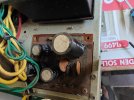
Do not mistake glue on the bottom of the capacitors to bond it to the PCB with a leaking capacitor. Glue is used (especially on larger caps) to secure it to the PCB to secure it against vibration. If you have a leaking cap, it might also have a bulging top. If you post a photo, we can determine if it is leaking.
 
When you first power it on, you may hear a slight pop as the capacitors are charging. Do you measure a DC voltage on the speaker terminals after power-on with the volume control turned all the way down?

Wait, you tested the capacitance using your multimeter using resistance, capacitance, or you measured the voltage using the meter? Was power on or off?
Do not mistake glue on the bottom of the capacitors to bond it to the PCB with a leaking capacitor. Glue is used (especially on larger caps) to secure it to the PCB to secure it against vibration. If you have a leaking cap, it might also have a bulging top. If you post a photo, we can determine if it is leaking.
Yes I measure DC voltage after it is turned on and the volume is all they way down. The speakers also made crackling noises.

I tested it with the multimeter set to resistance. What I see is that the resistance goes up, but does not go to OL and then it just goes down again.
But according to your information, I think it might have been glue indeed. Here's a picture of the psu board. None of the caps have bulging top as far as I can see?
 

Attachments

  • IMG20250202160112.jpg
    IMG20250202160112.jpg
    115.5 KB · Views: 13
Comment: Don't do the full recap until you find and fix the problem with DC on the speaker terminals, otherwise when it doesn't work you will have a difficult time isolating the problem. o_O

Follow the signal from the output of the Main Amp board to the speaker outputs. You will see that the signal passes through a DC blocking 2200uF capacitor (C003, C004) before it gets to the speaker terminals. Check to see if those two are bad (shorted) and replace and test for DC at the outputs again.

View attachment 3417587
I will do these first when I get the parts.
I'll keep you posted. Thanks :-)
 
Checking to see if you were able to solve this problem?
I have a (new to me) 1030 that has extremely low volume on the right side of the amp board. I have ruled out some possibilities including preamp transistors.
When I inject a 1k tone at the inputs of the P700 board the left side is good, right side is extremly low (only makes sound with a high input signal). I assume this tells me that the output transistors are ok on the right side(?)
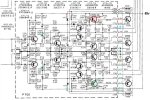
I've compared voltages between the good and bad side. Main clue right now is that voltages of H709 (bad channel) and H710 (good channel) don't match. On dim bulb, those voltages are as follows:
H710 E:20.6 / B: 22 / C:40.5
H709 E: 2.2 / B: 3.0 / C: 40.8
Any help would be most appreciated.
Thanks
 
I would be curious about the DC voltage at the cathode ends of H713 and H714 diodes (Marantz called them varistors). It can be tested at J707 and J708. If they are not close, then diode test the diodes to see if they act the same. If the voltages are close, then the problem is elsewhere.
 
Thank you for the response Steven.
They are not the same at all.
J707: 2.5
J708: 20.4
Does this point to bad varistors/diodes? I see they are the old "blob" stye. I would typically replace once I've solved the issue.
It appears that the left side rail-related voltages are very low.
here's the measurements on that side of P700 (on dim bulb)

J707: 2.5
J709: 45.8
J711: 2.46
J713: 1.87
J719: 0
J715: 1.74
J717: 1.7
J721: .6
J723: 0
J725/6: 0
J724: 0
J722: .36
J718: 21.02
J716: 20.58
J720: 0
J714: 20.75
J712: 21.29
J710: 46.6
J708: 20.4

I should also mention that I replaced C709/C710 as I discovered that one of the legs had corroded through.
Oddly, this was on the good side, but I believe was causing some distortion.
 
Last edited:
I guess I would test the output transistors to rule them out. Either pull and do the 6-way diode test on each one or use a transistor tester. Another alternative would be to swap the left side and right sight outputs and see if the weak channel switches sides. If it does not, outputs are probably OK. I would also be curious about the voltage measurements at both ends of R722 and R723 to see if 723 is low. Looking for the earliest place in the schematic that has the same voltage readings.
 
I’ll check those resistors when I get back to the workshop in a couple hours. TBH I was holding off on pulling transistors because they are soldered in on this unit.

It’s passing dim bulb, and there is some output on the right channel albeit very, very low. I assumed (probably wrongly) that the outputs were likely ok because of this, but perhaps that’s not how this unit is wired.

More to come.
Thanks.
 
thank you Dankik. I have the same handwritten, but this is so much better and accurate.

Stephen, I should have also asked exactly how you would suggest I swap the outputs? My unit does not include jumpers, so this would happen at the inputs to the P700 board?
 
I should also mention that I replaced C709/C710 as I discovered that one of the legs had corroded through.
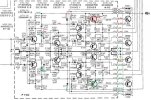
Please check the polarity of C709. That is on the bad side and may be where the low voltages come from (see schematic 1.74v vs 20.6v).
C709 (-) should connect to R715.
If that is OK, can you measure the transistor voltages of H701 vs H702?
Screenshot 2025-08-06 144311.jpg
 
I just realized that I misidentified the two matching resistors. It looks like they are R721 and R722 - not 722 and 723. Sorry about the confusion.
 
No, I thought the outputs were screwed to a heat sink and could be pulled and swapped without having to unsolder anything.
 
Resistor readings (
R721 39.51 (lead facing side of board) / 3.04 (lead facing in)

R722 40.9 (lead facing side of board) / 21.2 (lead facing in)

Both resistors measure the same ohms in circuit
 
Back
Top Bottom