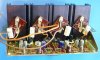
Main Amp Board (W23-010)
C1 - Original 100uF 25v / Now 100uF 35v (UKL1V101MPDANA)
C2 - Original 100uF 25v / Now 100uF 35v (UKL1V101MPDANA)
C3 - Original 10uF 10v / Now 10uF 25v (UKL1E100MDDANA)
C4 - Original 10uF 10v / Now 10uF 25v (UKL1E100MDDANA)
C5 - Original 22uF 25v / Now 22uF 35v (UKL1V100NDDANA)
C6 - Original 22uF 25v / Now 22uF 35v (UKL1V100NDDANA)
C7 - Original 47uF 3v / Now 47uF 25v (UKL1E470KED)
C8 - Original 47uF 3v / Now 47uF 25v (UKL1E470KED)
C11 - Original 100uF 3v / Now 100uF 25v (UKL1E101MPDANA)
C12 - Original 100uF 3v / Now 100uF 25v (UKL1E101MPDANA)
C13 - Original 100uF 50v / Now 100uF 63v (UPW1J101MPD)
C14 - Original 100uF 50v / Now 100uF 63v (UPW1J101MPD)
Q1 - Original 2SC870 / Now KSC1845FTA
Q2 - Original 2SC870 / Now KSC1845FTA
VR1 – 50K Ohm / Now 3386H-1-503LF (Bourns)
VR2 – 50K Ohm / Now 3386H-1-503LF (Bourns)
VR3 – 50 Ohm / Now (Bourns)
VR4 – 50 Ohm / Now (Bourns)
Managed to order VR3-VR4 as 50K... but had some spares in stock (mounted them on the bottom of the board due to configuration of the VR - turned out fine as they are easy to access at the bottom).
VR1-V2 as indicated earlier by others - the pots need more resistance. I put a 30K resistor in series.
Cap coupled amp so the common collectors on the output transistors were set to 50% of rail voltage. Bias was dialed up to 10mV (for 20ma) measured across one emitter resistor in each channel.



 but it ended up as a very nice amp.