• The move to the new server is done. There are some software and database maintenance updates in process. This has us passing the hat around to help out. We appreciate any donations. Seriously, even a dollar helps. The payment page may be found here - https://www.audiokarma.org/support.html

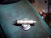
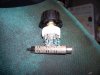
Proof of concept: An $8.01 passive preamp... in a cigar box!

my response

BWAHAHAHA! The ultimate in passive preamps. So compact it doesnt need a case!

parts; two lorlink 11 position switches, four female/male rca adapters, a bunch of 1/4 watt 1% tolerance resistors, silver jewelers wire, 2 knobs of your choice

other stuff; a dremel tool and cutoff wheels, a bunch of free time

optional stuff; beer

cut open two of the male ends and two of the female ends to solder jumper wires and then solder the two adapters together.

solder the resistors in place and loop silver jewelers wire around the other end of resistors and solder in place

insert in between component and amp, install beer :beer: and power up stereo :music:

yeah, I know its a bit more complicated than a couple of pots, but hey, I got lottsa spare parts and spare time,,
 

Attachments

  • Picture 046.jpg
    Picture 046.jpg
    114.3 KB · Views: 238
  • Picture 048.jpg
    Picture 048.jpg
    75.5 KB · Views: 132
  • Picture 050.jpg
    Picture 050.jpg
    112.8 KB · Views: 241
That is too cool! Encase it in clear acrylic & light it with multi colored leds- it's the next craze!
 
Hey folks, I am about to build one of these. I am hoping to have this and a couple of monoblocks ready for demo at the twangfest.

I do have a question. I am going to add a multi position selector switch. Anyone have an idea of what I need? A make before break or a break before make? Any suggestions as to what switch to use and a source. If you don't have a specific, I'll look one up at mouser, newark, digikey, etc.

I am aslo going to add an input/output loop. This way I can add an eq in line for tone controls.

More to come.
Mark
 
Jcricket- Thank goodness you're putting in a selector switch. I just don't see the point of a "preamp" that's just a volume control with no switching capability. Stereophile's been doing this lately too when they review headphone amps, calling everything a one-source linestage. What's the point? I have at least three sources in even my simplest system...

Nice work though Redboy, I really like the re-purposing of the cigar box...get a big ol Bakelite chicken head guitar amp knob on there and you've got a cool piece of gear!
 
I am thinking of a break before make selector switch. I also think I need at least five maybe six sets of inputs. One set of inputs on the front for an ipod(ick) for my wife and kid.
more to post later
 
I found the selector switch at AES. 6 position non-shorting dual pole.

I am looking at the Harry Hailer Schematic attached in this thread. Can anyone tell me what the function of the 11k resistor? If it is removed from the circuit, what happens?

I am asking, because I am thinking of replacing this with a 20k, and a 20k pot in parallel, thus in effect giving a second adjustment and essentially creating a balance function in the preamp.

Maek sense? Work?
Mark
 
Had my coffee now. Duh......
If the 11k resistor is removed you have zero resistance from the input to the output. The shunt/variable resistor will never bleed off voltage until it is actually a short to ground. So, if the 11k is removed, the shunt will not work and effectively beomes an on/off onl;y when moved to zero resistance.
 
The Harry Haller schematic:

series_shunt_pot_schematic.JPG


Redraw this yet again with a source (CDP, etc.). The source is shown as a simple voltage source with output impedance ZS.

series_shunt_pot_schem_2.JPG


The pot is shown as a variable resistor because that is how it is used. That is, of the three terminals in the pot, the wiper terminal and one of the other terminals are being used. The third terminal is not connected to anything.

Now, if the 11K resistor is removed (short-circuited, I think is what you are saying), you could end up short-circuiting the output stage of your cd player, or whatever the source is.

That is, if the pot were turned all the way down, ZPOT = 0, and ZAMP is short-circuited. Not only that, ZS (the output impedance of the source device) is connected to ground, and there could be a very high current demand on the output stage. This of course depends on the value of the source impedance.

With the 11K in the circuit, the source will see at least a 11K load (pot turned all the way down to ground). As the pot is turned up, the load seen by the source will increase from this base value of 11K, as will the signal voltage that appears across the amplifier inputs.

Next, a traditional volume control with a pot:

traditional_pot_schematic.JPG


The load seen by the source is R1 + (R2 || ZAMP). If ZAMP is much larger than the value of the pot, the load seen by the source is a constant R1 + R2, or the total potentiometer value, irrespective of the position of the wiper.
 
Thanks for the tutorial. I got it now.

I do have a question. In the schematic(one channel shown) the 100k pot is really a variable resitor to ground. In actual assembly, it is a dual gang variable resistor - one pot for each channel.

I would like to add a second pot to each channel. These pots would be enitrely sepoerate with seperate controls to facilitate the function of a blanace control. I think the easiest way would be to run the to variable resisotrs in series. Maybe a 10k and a 100k. The 10k would be the balance or "minor db cut" attenuation. The 100k would be the volume. I would set it up so that the 10k is set normally at zero ohms. If one channel or the other was a little louder, then you would add a few ohms to the circuit to "balance" it.

Sound like it would work?

Thanks!
 
I do have a question. In the schematic(one channel shown) the 100k pot is really a variable resitor to ground. In actual assembly, it is a dual gang variable resistor - one pot for each channel.

I would like to add a second pot to each channel. These pots would be enitrely sepoerate with seperate controls to facilitate the function of a blanace control. I think the easiest way would be to run the to variable resisotrs in series. Maybe a 10k and a 100k. The 10k would be the balance or "minor db cut" attenuation. The 100k would be the volume. I would set it up so that the 10k is set normally at zero ohms. If one channel or the other was a little louder, then you would add a few ohms to the circuit to "balance" it.

Sound like it would work?

I think it will work. If I understand you right, you want to wire another pot (wired as a variable resistor) in series with the 11K resistor, and then the shunt pot to ground (also wired as a variable resistor). You might use a linear taper pot for this purpose.

Another solution is to use dual mono shunt pots, but maybe that is not an option since you have already invested in the stereo pot.
 
I think it will work. If I understand you right, you want to wire another pot (wired as a variable resistor) in series with the 11K resistor, and then the shunt pot to ground (also wired as a variable resistor). You might use a linear taper pot for this purpose.

Another solution is to use dual mono shunt pots, but maybe that is not an option since you have already invested in the stereo pot.

I need to give up on thios stuff or get more sleep.

I was going to wire the second variable resistor in series with the 100k pot. I said I would wire it to be normally at 0 ohms. That is wrong. I need to wire it so that it would be at 10k ohms normally. If I need to turn down a speaker I drop the resistance on whichever side I need and bleed off a little voltage/current to ground.

This way I couls also set the pot at center or 5k ophms. I could increase decrease either side as needed to get the proper balance.


I could use two pots, I thought of that, but I hate that kind of set up. Makes me crazy.
 
Do I have this right?

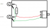
So I am looking to build the HH passive pre, and was wondering if my reading of schematics is accurate. I have drawn this physical representation of a single channel. Any help is appreciated. Thanks, and sorry for bringing an old thread back.
 

Attachments

  • harryhaller.png
    harryhaller.png
    13.5 KB · Views: 352
So I am looking to build the HH passive pre, and was wondering if my reading of schematics is accurate. I have drawn this physical representation of a single channel. Any help is appreciated. Thanks, and sorry for bringing an old thread back.
Looks good!
 
Sweet! Thanks, ill post pics when its done. Maybe I should start a new thread?
Sure! A new thread would be fun, especially if it has pics!

The tricky part will be figuring out how to connect the potentiometer - you need to determine which tab to connect to ground.

If you have a multimeter, turn the pot counterclockwise (to the lowest volume setting), and measure resistance from center tap (the wiper) to each of the outer taps in turn. The outer tap that measures zero resistance is the one to wire to ground.

Sorry if all this is redundant. I only point it out because I've wired these things backward before, and they don't work very well that way...

Good luck!
 
I could use two pots, I thought of that, but I hate that kind of set up. Makes me crazy.
To each is own. I built number of these things, each using two pots. I am now convinced that this design is an advantage.
 
I built it according to my picture I posted...

A few notes, comments, problems:

- I identified the lugs as per your directions, but I still got them backwards :lol:

- Running it on a Sansui R-410 into the tape input between my radio and cd player for now. Unfortunately it only has about 10% rotation before its max volume. The rest of the pot isn't doing anything.

- When no input is run, and it is turned up, there is tonnes of noise in the speakers. A horrible buzzing. It went away just now, but who knows if it will return.

I was scared to try it on my main system now, as my first try almost blew my place apart....

What'd I do wrong? Wrong pot? Or?
 
Hmm — get a meter. Cut all the wires you soldered. Put the meter on each pin and turn the pot. Isolate and identify the wiper — yet another time. Take 15 seconds to make a drawing and record where the wiper is.

That's a start. Next — find which pin shunts current to ground.

It has been so long, I hope that I have this right. Anyway, If I can build these things, anyone can. Trust me. I forget how many I've built. You will get it right, don't worry. You may have to get out the simple math and find what your optimum R should be for your pot/pots.
 
Back
Top Bottom