• The move to the new server is done. There are some software and database maintenance updates in process. This has us passing the hat around to help out. We appreciate any donations. Seriously, even a dollar helps. The payment page may be found here - https://www.audiokarma.org/support.html

PT on nuts or washers for heat dissipation ?

I thinking about that too, but noise, dust, and maintenance keeps me from going that route, for now.

But I done that with SS amps at full power.

The temp you quoted is nothing unusual for a tube amp anyway.. I've got some which have more temperature rise, some with less, all down to what the designer was doing trading off cost versus performance.
 
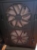
I use whisper fans in my gaming desk top computer. They have thin fine mess detachable screens. The screens catch dust very well. I've been using and upgrading that computer for years. The inside is almost completley dust free. The fans are pretty cheap, and quiet. Notice the dust on the screen. And the fan blades are clean and white.
 

Attachments

  • 20190308_102226.jpg
    20190308_102226.jpg
    29.3 KB · Views: 14
There is actually a reason for that. There is a chart I've seen (which I can't be bothered to locate just now) that shows the radiator efficiency and what color it is. Silver or white reduces output when the heat system or radiator is over-sized for the application. In the 20s there was a thing called the "fresh air movement", which basically was to keep windows open in the winter, and of course you'd need more heat output to make up for this. Once the Depression hit, there wasn't any money for that so the windows got shut and now you've got way too much heat system. Paint is cheaper than a new radiator, so there you go. There is a video on youtube of a guy discussing steam heating specifically in NYC and he talks about that. Its more interesting than it sounds.

I'm not shooting the messenger on this, but he is seriously confused about medicine, history, and steam heating, and his reliance on that paper is, furthermore, erroneous. I read through the paper and include some excerpts. Science!

The fact is that it really doesn't much matter what color the radiator, or a transformer, is painted because the surface is not hot enough to glow and most of the heat transfer is from convection not radiation.

Types of Radiators

What we call radiators come in two varieties:
Radiator which is a giant hunk of hollow cast iron through with hot water circulates. Because the radiator is constructed from segments, it better functions as a convector (below detailed) than a pure radiator. A radiator retains heat (thermal mass) when the heat is shut off at night. Even a giant hunk of metal is about 30 to 40% radiation and 60% to 70% convection, depending upon the number of segments which, in an apartment, is typically three or more.

Convector which is a pipe with many flat fins like the thin fins on an air conditioner, although through which hot water circulates, and which is covered by a perforated metal shield through which air circulates. A convector does not retain heat as the fins have very little thermal mass.​

Silve Paint and the Cited Paper

Here's what that paper actually says (yes, I read through it because I found the claims to be contrary to what I know about hot water heaters):
Emissive Tests of Paints for Decreasing Or Increasing Heat Radiation from Surfaces
BY W. W. Coblentz, Physicist, C. W. Hughes, Assistant Physicist
Bureau of Standards
March 13, 1924

The application of these data to house radiators is discussed. It is shown that, owing to the fact that house radiators are essentially convectors of heat, a gain of only 10 to 15 per cent in heat dissipation into the room may be expected by covering the surface of the radiator with a paint which is free from flakes of metals; for example, aluminum or bronze.

...

The emissive properties of paints of bronze, aluminum, iron oxide, zinc oxide, green and white enamel, terra cotta, etc., applied to steam house radiators were previously studied by Allen. 8 He found that the paints and enamels composed of nonmetals had practically (within 5 per cent) the same emissive properties. The paints containing flakes of aluminum or bronze had an appreciably (20 to 25 per cent) lower emissivity, which, as already stated, is to be expected from our knowledge of the low emissive properties of metals. The reason that he did not find a still lower emissivity for the metal paints is to be ascribed to the fact that his tests were made on segmented steam radiators, which are essentially convectors of heat, and, hence, the emissivity of the surface is of secondary importance.
...
In a 2-column radiator of 13 sections Allen found that of the total heat dissipated about 30 per cent was lost by radiation and about 70 per cent by convection. For a 4-column radiator the figures were 27 and 73 per cent, respectively. Allen calls this a convector of heat; but even in this case (loc. cit., p. 317) the aluminum paint dissipated only about 81 per cent (347 Btu per unit surface) as much heat as the nonmetallic surface (428 Btu) or the rusty or black paint surface.

These tests indicate that in a radiator consisting of a number of sections the heat carried away by convection between the sections is a large percentage (Allen's values range from 50 to 73 per cent, depending upon the type of radiator) of the total heat given out, and that the heat lost by radiation from the sides of the radiator is relatively of secondary importance. Hence, the use of a covering which is an inefficient emitter of thermal radiation is not so serious as it would appear from our tests of flat surfaces.
...
In conclusion it may be added that it is unnecessary to remove the old coat of aluminum paint before applying the coat of nonmetallic paint. This is owing to the fact that the aluminum paint, which has a high thermal conductivity, becomes simply part of the metal wall of the radiator.
So if the radiative portion declined by 20%, this would not reduce the overall heat transfer by more than 20% (reduction) x 30% (radiation) = 6% at the low end, or maybe 20% (reduction) x 40% (radiation) = 8% at the high end. The paper cites 10 to 15% as a maximum which seems to match.

In short, the silver doesn't reduce the overall temperature as much as is claimed because most of the heat is transferred via convection. As the paper states:
The temperature being low, this heat radiation is of long-wave lengths, invisible to the eye, and hence the color of the paint, whether red, yellow, green, or white, is no indication of its emissive properties. Aluminum oxide, white-lead paint (which is principally a carbonate of lead), and (green) chromium oxide have as high an emissivity as lampblack paint, and they have more pleasant and harmonious decorative properties as applied to steam pipes and radiators.

The silver paint, therefore, does reduce losses, but these are not significant as the radiator/convector is so hot a slight reduction in radiation doesn't matter for purposes of heating the apartment via convective heating. It does matter to ensure that heat is more even throughout a tall building, as the lower levels would tend to radiate more heat and thus reduce the heat available for higher floors. That's is likely the actual reason.

I can assure you that painted radiator pipes, whether white or silver, are hot enough to burn the skin from even brief contact and that any reduction from the paint is so trivial it is insignificant.

So the theory that this somehow reduced temperatures in a room by 20% is proven to be false. This is what happens when people don't actually read papers.

Reducing heat from radiators uses covers which restrict air flow, because, again, most heat transfer is convective.

Fresh-Air Theory Debunked

That purported "fresh air" theory is ridiculous. It's not even wrong.

It was well known by the 1920s that fresh air had no effect on influenza as is claimed, so the assertion that the influenza pandemic in 1917 created a "fresh air" movement where windows were opened to somehow prevent disease by deliberately wasting energy is ridiculous. That website's bad air theory is conflated with tuberculosis air treatments. Some TB patients were banished to the southwest, while others were stashed in caves. The Vitamin D deficiency must have been horrendous.

By 1917 it had been at least a hundred years since people believed that bad air caused disease. In the mid 1700's the Italians believed this, hence the name for a plasmodium falciparum infection as "malaria", literally "mala aria", i.e. bad air. Benjamin Rush—who killed George Washington by bleeding, purging, and poisoning with mercury—believed in the 1700's that Yellow Fever originated from rotting coffee, not mosquitoes. The original name of "influenza" is from "influence" because it was once believed that bad star positions caused outbreaks of disease.

Yet by 1917 it was well known the cause of influenza was an infectious agent. Much scientific research occurred to determine the route for infection. The idea that medical professionals in 1917 were so stupid as to believe disease was caused by bad air is just ignorant of how science and medicine worked. For example, in 1882 Koch presented his famous paper, Die Ätiologie der Tuberculose, which proved that tuberculosis was caused by mycobacterium 100% of the time. Disease agents were known, it was the effective treatments that were not available.

BTW: My granduncle was an Army doctor in Europe during WWI, treating soldiers with influenza. He contracted influenza and died from it. My grandfather (other side of the family) was also an Army doctor, but he didn't contract influenza. Something like 30% of soldiers came down with it, but the government suppressed this information from Americans. Truth is always the first casualty.

Why Windows Were Opened

Radiators and convectors emit so much heat that the apartment or house became oppressively hot, a problem with us to the present day.

Radiators and convectors typically have a valve to control the flow of hot water through the radiator and therefore the amount of heat emitted. Turn it down, lower heat. I generally turn my valves off because the risers, which I've insulated with the circular expanded/fused fiberglass insulation, are hot enough to keep my apartment at 85 degrees without my AC running. Without that it would be 100 degrees. From white-painted risers. No, I'm not joking. In the winter I run my AC fan to keep the temperature in the 70s. The compressor does not cycle, but the fan brings air past the heat exchanger which remains cool because the outside ambient air is cold.

Residents with hot-water heat open the windows for good reason: the valves are often frozen because of poor maintenance and the heat output is typically excessive and uncontrollable even with the valves off. I used to adjust my valves with a slipjoint pliers before a building-wide valve replacement two years ago. Others just opened the windows. When we had temperatures in the 20s I would open the valves with a pliers; now I may control the valve by hand.

Buildings are required by the building code to maintain a certain amount of heat. So if a change in temperature were truly desired and desirable to save lives, it would have been legislated as reducing valves in each room. Otherwise the landlord would have been in violation of the legal heating requirements and would have been fined. Back in those days energy, typically coal, was expensive. Heat and hot water have always been one of the most expensive parts of running a building.

TL/DR

The application silver paint has no tie to the influenza epidemic. It is nonsense. This was simply a means to slightly reduce radiation, and thus prevent heat losses on lower floors which would reduce the heat to higher floors and make the lower floors even more oppressive. But it has very minor effects.

 
I use whisper fans in my gaming desk top computer. They have thin fine mess detachable screens. The screens catch dust very well. I've been using and upgrading that computer for years. The inside is almost completley dust free. The fans are pretty cheap, and quiet. Notice the dust on the screen. And the fan blades are clean and white.

Yes, those whisper fans are amazing to keeping tube equipment cool.

A slim 120mm fan on bottom plate maybe could be silent and effective, but small fans that runs at high rpm no.

Me, too. I've used the larger fans which rotate at lower RPM for lower noise.

Remember, the fans work better at pull than push.
 
I am thinking about adding a SS full wave rectifier between the PT and tube rectifier inputs to diminish or avoid such failures.

Eventually, if there is a failure downstream, the SS rectifier can fail open instead of the PT.

The rectifier will not, however, fail as an open. Most rectifiers will carry more current than the B+ secondary.

A small fuse is the answer. Between the transformer and rectifier. Relying on components which are not fuses to open is bad engineering. Most resistors will take many times their rated wattage for long enough, sometimes hours, to burn out a transformer winding.

The advantage of adding diodes to a tube rectifier is in reducing PIV stress, which increases the rectifier's lifespan.
 
I am interested about adding fuses to the HV secondaries.

Could someone please tell me what value of 250V fuses should I use for each of the secondaries wires to be safe ?

It's better if the fuses blows slightly too quickly than too late, but instead of ordering and testing small values and blown them, if someone can tell the approx. right value or already have a generic value for that kind of circuit would help.

index.php
 
The 5Z3P is the Chinese version of the 5U4?

The schematic rates the choke for 250 mA maximum, so the current is certainly not going to be more than that. Oh, wait a minute, it's ChiFi, yeah, one would need to calculate all the tube draws to determine if that purported value is honored. What was I thinking!

Flippancy aside, you could ask the vendor for the current specifications.

Or you could just guess at 200 mA for the B+ and see if the fuse blows. I'd want the fuse to early blow to protect the transformer and rectifier. Fuses will tolerate some overload for a bit of time, so it's good to slightly undersize. (Unless it's the fuse in an apartment which keeps the AC running...) The manufacturer's specifications will detail the times.
 
5Z3P is a 5U4G , but I mostly use 5U4GB

I have the 20mm 250V 200mA quick acting fuses but not the fuses holders, maybe I can solder the fuses directly on sockets and order holders later.

Thanks.
 
Last edited:
Finally the fuses I thought was 200mA was 500mA , so I ordered 200mA fuses, fuses holders, screws, nuts, washers etc...

This cheap from the start amp require lots of love to make it better, but after I think I will love it.
 
I'm not shooting the messenger on this, but he is seriously confused about medicine, history, and steam heating, and his reliance on that paper is, furthermore, erroneous. I read through the paper and include some excerpts. Science!

The fact is that it really doesn't much matter what color the radiator, or a transformer, is painted because the surface is not hot enough to glow and most of the heat transfer is from convection not radiation.

Types of Radiators

What we call radiators come in two varieties:
Radiator which is a giant hunk of hollow cast iron through with hot water circulates. Because the radiator is constructed from segments, it better functions as a convector (below detailed) than a pure radiator. A radiator retains heat (thermal mass) when the heat is shut off at night. Even a giant hunk of metal is about 30 to 40% radiation and 60% to 70% convection, depending upon the number of segments which, in an apartment, is typically three or more.

Convector which is a pipe with many flat fins like the thin fins on an air conditioner, although through which hot water circulates, and which is covered by a perforated metal shield through which air circulates. A convector does not retain heat as the fins have very little thermal mass.​

Silve Paint and the Cited Paper

Here's what that paper actually says (yes, I read through it because I found the claims to be contrary to what I know about hot water heaters):
Emissive Tests of Paints for Decreasing Or Increasing Heat Radiation from Surfaces
BY W. W. Coblentz, Physicist, C. W. Hughes, Assistant Physicist
Bureau of Standards
March 13, 1924

The application of these data to house radiators is discussed. It is shown that, owing to the fact that house radiators are essentially convectors of heat, a gain of only 10 to 15 per cent in heat dissipation into the room may be expected by covering the surface of the radiator with a paint which is free from flakes of metals; for example, aluminum or bronze.

...

The emissive properties of paints of bronze, aluminum, iron oxide, zinc oxide, green and white enamel, terra cotta, etc., applied to steam house radiators were previously studied by Allen. 8 He found that the paints and enamels composed of nonmetals had practically (within 5 per cent) the same emissive properties. The paints containing flakes of aluminum or bronze had an appreciably (20 to 25 per cent) lower emissivity, which, as already stated, is to be expected from our knowledge of the low emissive properties of metals. The reason that he did not find a still lower emissivity for the metal paints is to be ascribed to the fact that his tests were made on segmented steam radiators, which are essentially convectors of heat, and, hence, the emissivity of the surface is of secondary importance.
...
In a 2-column radiator of 13 sections Allen found that of the total heat dissipated about 30 per cent was lost by radiation and about 70 per cent by convection. For a 4-column radiator the figures were 27 and 73 per cent, respectively. Allen calls this a convector of heat; but even in this case (loc. cit., p. 317) the aluminum paint dissipated only about 81 per cent (347 Btu per unit surface) as much heat as the nonmetallic surface (428 Btu) or the rusty or black paint surface.

These tests indicate that in a radiator consisting of a number of sections the heat carried away by convection between the sections is a large percentage (Allen's values range from 50 to 73 per cent, depending upon the type of radiator) of the total heat given out, and that the heat lost by radiation from the sides of the radiator is relatively of secondary importance. Hence, the use of a covering which is an inefficient emitter of thermal radiation is not so serious as it would appear from our tests of flat surfaces.
...
In conclusion it may be added that it is unnecessary to remove the old coat of aluminum paint before applying the coat of nonmetallic paint. This is owing to the fact that the aluminum paint, which has a high thermal conductivity, becomes simply part of the metal wall of the radiator.
So if the radiative portion declined by 20%, this would not reduce the overall heat transfer by more than 20% (reduction) x 30% (radiation) = 6% at the low end, or maybe 20% (reduction) x 40% (radiation) = 8% at the high end. The paper cites 10 to 15% as a maximum which seems to match.

In short, the silver doesn't reduce the overall temperature as much as is claimed because most of the heat is transferred via convection. As the paper states:
The temperature being low, this heat radiation is of long-wave lengths, invisible to the eye, and hence the color of the paint, whether red, yellow, green, or white, is no indication of its emissive properties. Aluminum oxide, white-lead paint (which is principally a carbonate of lead), and (green) chromium oxide have as high an emissivity as lampblack paint, and they have more pleasant and harmonious decorative properties as applied to steam pipes and radiators.

The silver paint, therefore, does reduce losses, but these are not significant as the radiator/convector is so hot a slight reduction in radiation doesn't matter for purposes of heating the apartment via convective heating. It does matter to ensure that heat is more even throughout a tall building, as the lower levels would tend to radiate more heat and thus reduce the heat available for higher floors. That's is likely the actual reason.

I can assure you that painted radiator pipes, whether white or silver, are hot enough to burn the skin from even brief contact and that any reduction from the paint is so trivial it is insignificant.

So the theory that this somehow reduced temperatures in a room by 20% is proven to be false. This is what happens when people don't actually read papers.

Reducing heat from radiators uses covers which restrict air flow, because, again, most heat transfer is convective.

Fresh-Air Theory Debunked

That purported "fresh air" theory is ridiculous. It's not even wrong.

It was well known by the 1920s that fresh air had no effect on influenza as is claimed, so the assertion that the influenza pandemic in 1917 created a "fresh air" movement where windows were opened to somehow prevent disease by deliberately wasting energy is ridiculous. That website's bad air theory is conflated with tuberculosis air treatments. Some TB patients were banished to the southwest, while others were stashed in caves. The Vitamin D deficiency must have been horrendous.

By 1917 it had been at least a hundred years since people believed that bad air caused disease. In the mid 1700's the Italians believed this, hence the name for a plasmodium falciparum infection as "malaria", literally "mala aria", i.e. bad air. Benjamin Rush—who killed George Washington by bleeding, purging, and poisoning with mercury—believed in the 1700's that Yellow Fever originated from rotting coffee, not mosquitoes. The original name of "influenza" is from "influence" because it was once believed that bad star positions caused outbreaks of disease.

Yet by 1917 it was well known the cause of influenza was an infectious agent. Much scientific research occurred to determine the route for infection. The idea that medical professionals in 1917 were so stupid as to believe disease was caused by bad air is just ignorant of how science and medicine worked. For example, in 1882 Koch presented his famous paper, Die Ätiologie der Tuberculose, which proved that tuberculosis was caused by mycobacterium 100% of the time. Disease agents were known, it was the effective treatments that were not available.

BTW: My granduncle was an Army doctor in Europe during WWI, treating soldiers with influenza. He contracted influenza and died from it. My grandfather (other side of the family) was also an Army doctor, but he didn't contract influenza. Something like 30% of soldiers came down with it, but the government suppressed this information from Americans. Truth is always the first casualty.

Why Windows Were Opened

Radiators and convectors emit so much heat that the apartment or house became oppressively hot, a problem with us to the present day.

Radiators and convectors typically have a valve to control the flow of hot water through the radiator and therefore the amount of heat emitted. Turn it down, lower heat. I generally turn my valves off because the risers, which I've insulated with the circular expanded/fused fiberglass insulation, are hot enough to keep my apartment at 85 degrees without my AC running. Without that it would be 100 degrees. From white-painted risers. No, I'm not joking. In the winter I run my AC fan to keep the temperature in the 70s. The compressor does not cycle, but the fan brings air past the heat exchanger which remains cool because the outside ambient air is cold.

Residents with hot-water heat open the windows for good reason: the valves are often frozen because of poor maintenance and the heat output is typically excessive and uncontrollable even with the valves off. I used to adjust my valves with a slipjoint pliers before a building-wide valve replacement two years ago. Others just opened the windows. When we had temperatures in the 20s I would open the valves with a pliers; now I may control the valve by hand.

Buildings are required by the building code to maintain a certain amount of heat. So if a change in temperature were truly desired and desirable to save lives, it would have been legislated as reducing valves in each room. Otherwise the landlord would have been in violation of the legal heating requirements and would have been fined. Back in those days energy, typically coal, was expensive. Heat and hot water have always been one of the most expensive parts of running a building.

TL/DR

The application silver paint has no tie to the influenza epidemic. It is nonsense. This was simply a means to slightly reduce radiation, and thus prevent heat losses on lower floors which would reduce the heat to higher floors and make the lower floors even more oppressive. But it has very minor effects.

Retrovert's posts are the greatest!
 
The schematic indicates circuit stages draw about 78mA total, and the amp runs in class A.

PSUD2 indicates the power transformer secondary CT current is about 140mArms.

If it is assumed you have purchased an IEC compliant 250VAC 5x20mm 200mA slow blow (T) fuse, and use it in the CT link, then PSUD2 indicates it would pass 780mArms in first 20ms, 850mArms in first 150ms, and 490mArms in first 600ms after turn on. The 150ms current level is above the spec level for a 200mA fuse, so you would run the risk of possible fuse blowing on power up.

If it is assumed you have purchased a UL284 compliant 250VAC 5x20mm 200mA slow blow (T) fuse, then the 140mArms operating current is just below the allowed 150mA operating level max for a 200mA rated fuse. Unfortunately the UL284 spec doesn't provide any definition as to whether the fuse would survive power up - that will be suck-it and see.

Alternatively, you could install a fuse in each anode leg, as that path has about 100mArms in it.

If you were really trying to protect your amp from collateral damage, I'd start by adding two series connected IN4007 in series with each anode of the rectifier valve, and then add fusing.

Wrt the chassis heating, you indicate the base of the amp chassis has 'good' vents, but that isn't a clear description without a photo or drawing, and you make no comment of how you locate the amp (eg. in an enclosed equipment cabinet, or on a large shelf with no vents in the shelf) and how much spacing is between the amp base and whatever is under the amp.
 
The bottom plate have a few long appeartures on a good surface, and the amp have 1cm high feets, sits on a wood chair for now.

But the top of the amp only have small appertures around the tubes , what you see on the earlier picture, the KT88 vents are half hidden under the KT88 bases, but I think the worst is that there is no vent at all around the power transformer.

For soft start-up, I already have two 120 ohms 2A thermistors in series with the AC input.

I didn't think about purchasing slow blow fuses, at least the price was correct,

Thanks for your calculations. I will purchase higher rated fuses.

So I think I will buy 250mA slow blow fuses.

Edit: And yes, my intention was to put a fuse on each anode, then slow blow 250mA will be high.
 
Last edited:
Fuses do not, alas, instantly blow at the rated current. That only occurs in the wonderful word of Fantasy Fuses. It's a wonderful place; cake and pastry do not have calories, the highways are never crowded, mass transit actually works, elected officials are honest and responsive, and one can pick up Mullard 12AX7's free. I've never been to that place.

Fuses basically boil down into a few different types: slow blow, fast blow, very fast blow. The name indicates the amount of time overload current must exists before the fuse will blow. This is never a hard and fast value, and it often depends on history of overload pulses.

Fuse behavior is generally distilled into time-current characteristic which differs by the type of fuse.

The slow-blow is typically used with motors, compressors, and magnets, all of which have a giant current spike occurs at startup which then reduces. (This is why the dishwasher or AC blows a fuse or trips a circuit breaker when the motor turns on.) A tube's heater current is a lot like this, because, being a positive temperature co-efficient device, the cold resistant is zero and the hot resistance is quite high. So the heater acts like a dead short at startup, often with a current demand up to ten times its nominal rating.

A slow-blow fuse can tolerate significant overload for some time, minutes even hours. That's key. Using a slow-blow to protect a rectifier or transformer will not work, as the rated current will be grossly exceeded, by many times the current limits for the cathode or the winding, before the fuse gives up and opens.

UL rates a fast-acting fuse as one which typically opens within five seconds maximum when subjected to a minimum of twice the rated current. IEC rates based upon ten times the rated current.

For a normal fuse a current load only slightly greater than the rated carrying current the fuse may take minutes or even hours to blow.

To reduce the time to blow the general rule is to undersize the fuse a bit, typically about 70% or so of the rated load. That is high enough to avoid what the fuse companies call a "nuisance blow". Protecting a transformer or tube rectifier requires a reasonably fast open, because the goal is circuit protection, not to avoid a fire from an overheated device.

All of this must be de-rated for operating temperature, of course, because a fuse cools to the ambient so higher temperatures mean faster blowing. This typically does not affect HiFi because it generally does not operate at these extremes, although the tubes and transformers can be quite hot. Fuses should not be placed adjacent to hot components.

The major fuse companies offer wonderful treatises on how fuses work. I found them highly educational and the end of much of the misinformation that I was taught about circuit protection or picked up on the street.
 
Here's an example of why slow-blow is not the right solution for rectifier and transformer protection.

My apartment formerly had fuses. When my AC compressor would start up on a hot day, when the voltage was slightly lower because of brownouts, the higher current load would blow the fuse. Every single time. I replaced the fuse with a slow-blow and this ended the problem. Why? Because the additional time constant was enough to withstand the heating from the compressor's current spike. The slow-blow would tolerate that over-current for many minutes, when the duration was but a few seconds.

Now, if this current load were a shorted electrolytic capacitor the over-current would continue until something melted, either the fuse, the rectifier, or the B+ secondary winding. So by the time a slow-blow on the B+ secondary opened the rectifier cathode would have been running into a dead short (electrolytic failure as short) for too long (exceeded its current rating) and it would have been destroyed, along with the B+ winding from over-current.

A fast blow fuse, slightly undersized, would instantly blow as the current rose to either the rectifier's maximum limit or the transformer's maximum limit, preventing damage and protecting expensive and hard to source (and replace) components.

Slow-blow is only valuable in HiFi for a filament winding because, again, the PTC heater acts like a dead short on startup, exceeding the typical operating current. This is why fuses in HiFi often appear grossly oversized; the rating includes the heater startup period where the current may be ten times normal draw. Filament windings are designed to briefly endure such overloads, while B+ windings are not.
 
Ok, so I will try the 200mA quick acting fuses (one on each anode).

I removed one of the two thermistors so it left only one 120 ohms thermistor, that second thermistors was causing too much heat, I hope the startup will still be soft enough with only one thermistor for the fuses not to blow.
 
Even fast acting have a curve. The higher above the rated current it is, the faster it will open.
 
Ok, so I will try the 200mA quick acting fuses (one on each anode).

I think the stead-state current is a lot lower than that, and the rectifier and winding should support that long enough for the fuse to blow, so this should be about right.

Electrolytic capacitor failure is uncommon. But so are replacement parts, and as time progresses the supply will only become more limited. :(

I removed one of the two thermistors so it left only one 120 ohms thermistor, that second thermistors was causing too much heat, I hope the startup will still be soft enough with only one thermistor for the fuses not to blow.

No worries as no current spike occurs for B+ at turn-on. The spike occurs for the heaters. This is why lightbulbs fail at turn-on. The current inrush into a cold tungsten filament is as much as ten times normal current draw, and it forces a substantial current through already hot regions, heating to the point of failure.
 
Even fast acting have a curve. The higher above the rated current it is, the faster it will open.

Correct, and that's a good point.

I was amazed when I first learned that fuses do not instantly blow because I thought that a fuse instantly opened at its rated current. After all, isn't that the purpose? (None of this was covered in school.) Then I read the Bussman and LittleFuse papers and learned, nope, it's a curve and it gets even more complex when one factors in the pulse current. This is also why the mains fuse may blow, or the breaker may trip, before a smaller slow-blow fuse in equipment blows.

But I think what we must consider in this case is the time function for the amount of current over the rated current, what happens in the fault for which we are trying to provide protection, and how much over-current may the rectifier and transformer withstand without damage.

Here's some speculation and hand-wavy argument on the back of the napkin, which is wet with condensation (ice in the scotch) so the ink's a little blurry.

For a fuse to fail in five seconds or less UL requires the fuse blow at twice the rated current. So if the rectifier were fused at, say, 500 mA, a commonly available value, the five seconds would likely be enough to damage the rectifier's cathode and would probably cause an arc event which further damaged the cathode and greatly shortens its lifespan. The maximum current for the rectifier is less than half that, so how long can it withstand a peak. (shrug) I dunno. The papers I've read suggest that small pulsed over-current conditions damage the cathode. While those were very high energy, typically radar, the short-circuit condition is likely comparable.

The transformer B+ winding would likely survive that short overload if it output higher current, since the overload prior to interruption would not be that much beyond its rated capacity, but a lower-current winding would likely not as its thin wire would be overheated.

Now, let's drop that down to 200 mA. Twice that is 400 mA, certainly doable in a short (but qualified as per the argument below set forth). Can the transformer and rectifier withstand that for a few seconds? Time drops because the over-current is going to be much higher.

The question is what does the capacitor failure look like? Is it an instantaneous short which would pull so much current the fuse would blow in fewer than five seconds? Or is it an ever-increasing amount of current over a few seconds, enough to keep the fuse intact past the point of rectifier failure?

Dunno.

Someone needs to short out a few rectifiers and transformers come back with some data. :)
 
The bottom plate have a few long appeartures on a good surface, and the amp have 1cm high feets, sits on a wood chair for now.

But the top of the amp only have small appertures around the tubes , what you see on the earlier picture, the KT88 vents are half hidden under the KT88 bases.
What is the total aperture area of the long slots in the base, and the total aperture of the holes around the valve sockets, and the total aperture of the proposed raised transformer (3mm x the internal transformer perimter aperture, ie. not the transformer external perimeter)? Are the holes around each valve socket really 50% blocked, or is it that you can't easily see them? At the moment, the air flow description of natural (chimney) venting of air within the chassis is difficult to appreciate.

For soft start-up, I already have two 120 ohms 2A thermistors in series with the AC input.
Why did you add two, and now one, thermistors to the AC circuit? Did you measure the power transformer winding resistances, and mains AC rms current for starters?
 
Back
Top Bottom