• The move to the new server is done. There are some software and database maintenance updates in process. This has us passing the hat around to help out. We appreciate any donations. Seriously, even a dollar helps. The payment page may be found here - https://www.audiokarma.org/support.html

QR-6500 re-cap

KeithD

AK Subscriber
Subscriber
I'm building a list of components to replace in a QR-6500. I noticed there are oil caps on the list of "Other components" in the service manual:

C012 and 013 0.01 µF/400V
C014 0.033 µF/600V
C027 0.0047 µF/600V
C028 0.01/500V

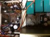
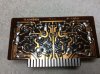
I found C012 and C013 on the underside, each connected to a large diode.
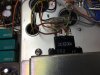
IMG_1184.JPG

I've read these Suzuki oil caps tend to go bad, so first question is should I be replacing these, and if so, what are the replacements?
 
Register to hide this ad
Found C14 and C27. Not Suzuki caps, so maybe they can stay? Any recommendations on the Suzukis?

4F19488D-9158-4273-BE72-DE46DC2A69F4.jpeg
 
Yes, I was surprised by that. Why is the voltage rating so high for that position?
See my edited post above. ;)

A very high DC voltage rating is equivalent to a much lower AC voltage rating, and to include a significant extra safety margin. You could probably get away with a somewhat lower DC voltage rating most of the time. But if you get a spike or a brief surge on the AC line, heaven help the DC rated capacitor. ;)
 
Last edited:
Sorry, I think I was looking at the wrong picture/wrong post when I made my reply.

I re-edited my post for clarity - sorry if I have orphaned one of your post quotes. :)

I'll go back to sleep :D
 
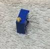
For trimmers, AC balance is 200 kΩ. I was thinking Bourns 3362W-1-204 or 3362X-1-204LF. Difference seems to be direction of turn, though it's not clear from the data sheet which is CW and which is CCW. Any advice on those?

I was planning to use 3386H-1-102LF for the Bias trimmers (1 kΩ) as I have those on hand. Would be nice to find larger (size) ones, though. The originals are quite wide.
 
I'm thinking this would work?


MKS4G021003C00KSSD
I use Axial Poly film caps like these for those applications.
I do quite a bit of tube gear and they are full of those types of caps....

Not a cheap exercise when you have an amp full of them, but just a few like this, no problem!!

What you can also to is use some plastic sleeve on the legs as well.
Make sure you test them for the foil vs non foil end.

https://www.mouser.com/ProductDetail/KEMET/A70PQ2680AA00J?qs=gt1LBUVyoHklUuL7fzWiDQ==
 
Leads are going to be a little short I think. I normally use Panasonic box caps.

Can't go by the picture. Cap lead spacing is 10 mm and length is 13 mm in the specs.

I use Axial Poly film caps like these for those applications.
I do quite a bit of tube gear and they are full of those types of caps....

Not a cheap exercise when you have an amp full of them, but just a few like this, no problem!!

What you can also to is use some plastic sleeve on the legs as well.
Make sure you test them for the foil vs non foil end.

https://www.mouser.com/ProductDetail/KEMET/A70PQ2680AA00J?qs=gt1LBUVyoHklUuL7fzWiDQ==

Hard to see in the picture in my first post, but the cap is covered in a plastic sleeve, and each leg is covered in a plastic tube. However, I think radial makes way more sense. The cap leads go to the two inner tabs. I assume they used an axial cap because that's what was available at the time, but to use one now you'd have to bend the leads all the way around to connect to the two inner tabs.
 
Hard to see in the picture in my first post, but the cap is covered in a plastic sleeve, and each leg is covered in a plastic tube. However, I think radial makes way more sense. The cap leads go to the two inner tabs. I assume they used an axial cap because that's what was available at the time, but to use one now you'd have to bend the leads all the way around to connect to the two inner tabs.
I see your reasoning there, and it makes a lot of sense.
Sansui might have had a bunch of those caps they needed to use up, so they put them in this amp, who knows..
Your cap selection is a good one, make sure you get the ones with the long legs, makes it easier to work with them that way.
 
Starting the re-cap. Those Wima caps fit in nicely on the large diodes.

C79B9925-0FDB-4544-A1F4-308EF6A21439.jpeg

Next up will be the power supply board.

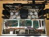
43CAF500-6924-4423-86E7-0AF853E8856D.jpeg

This is on the underside, but the tuner is on a "tray" and can be removed as one unit giving access to the underside of the PS and quad boards.

248BB4EB-2A9D-4872-B489-E6CB3110135D.jpeg
CBA4537D-EBEE-4053-830F-D230D5077FB1.jpeg

Lots and lots of e-caps in here; all gray colored Elna. To start I am just replacing e-caps on the PS and driver boards, as well as the trimmers. With this modular design, you can really get access to almost anything in there.
 
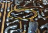
Next is the front driver board. This board is surprisingly clean for being 50 years old. I don't even see any corrosion on the copper band around TR803/4 and TR808/9.

IMG_2774.JPG IMG_2775.JPG IMG_2776.JPG IMG_2777.JPG

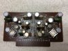
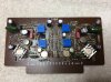
Of course, all the e-caps and trimmers need to go. Here is the board stripped of those parts. Very clean and no glue! Sansui did a fantastic job of clearly labeling these boards, much better than in later years, IMHO. I did not find any mistakes in the board markings.

IMG_2778.JPG

First challenge is replacements for VR802 and 804. The originals were quite large, and the spacing to the outer posts is very wide. I purchased Bourns multi-turn for replacements, 3/8" wide, part number 3296P-1-102LF (too bad they don't have anything bigger). With some measuring and matching, I got a fit for width, with enough of the leg sticking through the (large) hole to make a solder contact.

fullsizeoutput_5c2.jpeg fullsizeoutput_5c5.jpeg
 
Since the adjustment screw is on the right side of the trimmer, I needed to pay attention to the location of VR801 and 803. The original trimmers were mounted directly over VR802 and 804; however the latter were much larger and stood out from the board much further than VR801/3 allowing easy adjustment. However, the multi-turn replacements for VR801/3 are the same size as VR802/4 replacements. Thus, I had to make sure VR801/3 were "offset" from the trimmers mounted below so that the lower trimmers could be adjusted. Not a big deal, really, since the hole spacing for the upper trimmers is much closer together, allowing enough latitude in placement.

IMG_2781.JPG

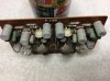
It's close, but enough room for a small screwdriver. Of course, it doesn't end there. C807 is located directly over VR802, so that cap needs to be bent over a bit to give clearance for a screwdriver. Here's the finished board with all caps in place.

IMG_2782.JPG IMG_2783.JPG

Reinstalled the board and after checking on DBT, made adjustments on mains power. Rear driver board is identical, so that should go pretty smoothly now that I've got the front done.
 
Back
Top Bottom