

You are using an out of date browser. It may not display this or other websites correctly.
You should upgrade or use an alternative browser.
You should upgrade or use an alternative browser.
QR-6500 re-cap
- Thread starter KeithD
- Start date
-
- Tags
- qr 6500 suzuki capacitors


Thanks Kev, I was glad it worked out. I was not sure it would.
Set the bias, though it tended to drift down a bit over time (is this normal?) SM calls for 25-30 mA, so I set it at the high end.
I don't have an 8Ω/40W resistor called for in SM to set the output adjustment, so I went with setting the voltages via the schematic. PS to the board per schematic is 50V, with 30V spec'd at the VR, or 60% of the supply voltage. Measuring supply voltage at R809/829 I had 57V, so should be 34.2V at the VR. Adjusted each channel to that setting.
Set the bias, though it tended to drift down a bit over time (is this normal?) SM calls for 25-30 mA, so I set it at the high end.
I don't have an 8Ω/40W resistor called for in SM to set the output adjustment, so I went with setting the voltages via the schematic. PS to the board per schematic is 50V, with 30V spec'd at the VR, or 60% of the supply voltage. Measuring supply voltage at R809/829 I had 57V, so should be 34.2V at the VR. Adjusted each channel to that setting.
Rear channel driver board done. I decided to also replace TR801 and TR806 (2SC458LG) with KSC1845F matched pairs on both boards. I was not having an issue with those, but the legs on all of them had turned black, and it was likely a matter of time before they acted up.
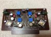
Was a bit better at making a clear path to adjust the lower trimmers.

Ended up with one broken trace that I did not see right away, but bright DBT make me inspect the board more closely. Easy fix and all is well!
All original caps measured a bit high 17 to 45% above rated value, not bad really. ESR was worst on the small caps. Highest was about 9 Ω, with most in the 1.2 to 3 Ω range.
Was a bit better at making a clear path to adjust the lower trimmers.
Ended up with one broken trace that I did not see right away, but bright DBT make me inspect the board more closely. Easy fix and all is well!
All original caps measured a bit high 17 to 45% above rated value, not bad really. ESR was worst on the small caps. Highest was about 9 Ω, with most in the 1.2 to 3 Ω range.

nicholas2381
Super Member

Decided to look deeper at the electrolytic capacitors I pulled out of the power supply and driver boards. I usually measure capacitance of the old caps after I've pulled them out, mostly out of curiosity, but also as an indication if other boards need to be re-capped. Most of the e-caps I pulled out were not too far out of spec (±20%) or even in spec with respect to capacitance. However, I used my little electronics tester to measure ESR (Equivalent Series Resistance) of each cap as well. As can be found on Wikipedia, "A very serious problem, particularly with aluminium electrolytics, is that ESR increases over time with use; ESR can increase enough to cause circuit malfunction and even component damage, although measured capacitance may remain within tolerance." Thus with most caps close to spec, and this receiver being 50 years old, I was curious how the ESR would measure, and then compare that to the specified ESR of the replacements caps. Here is my data table for F-1373 Power Block. After measuring ESR of the cap I pulled out, I then just calculated an ESR Ratio: (old cap ESR)/(new cap ESR). Of course if the values were the same, the ratio would be 1. I was shocked how much higher the ESR for the old caps were as compared to the new caps.

As seen, the ESR ratio ranges from 11 to 1,197! This is a good illustration of how an e-cap can be in spec or close to it for capacitance, but have developed a high resistance. Now, I don't know the ESR of these caps when they were new at the factory. I can only assume they were not as good as the Nichicon replacements I used, and are common today. But, certainly, they were far lower than the values I measured. Others far more knowledgeable than me can comment on how increasing ESR affects these circuits, but I have read many times that increasing ESR is the most common mode of e-cap failure rather than large changes in capacitance.
The e-caps from the driver boards did not have as high an ESR ratio as the PS, but still concerning for many of the caps.
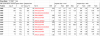
Again, all capacitance values were high, but not too far from spec.
As seen, the ESR ratio ranges from 11 to 1,197! This is a good illustration of how an e-cap can be in spec or close to it for capacitance, but have developed a high resistance. Now, I don't know the ESR of these caps when they were new at the factory. I can only assume they were not as good as the Nichicon replacements I used, and are common today. But, certainly, they were far lower than the values I measured. Others far more knowledgeable than me can comment on how increasing ESR affects these circuits, but I have read many times that increasing ESR is the most common mode of e-cap failure rather than large changes in capacitance.
The e-caps from the driver boards did not have as high an ESR ratio as the PS, but still concerning for many of the caps.
Again, all capacitance values were high, but not too far from spec.
nicholas2381
Super Member
Nice work, KeithD. Interesting stuff!
Before doing any restoration work I was getting a "pshhht" sound out of some speakers when the power was turned off. Replacing TR801/806 (2SC458JG) with KSC1845F solved most of that, but still getting a bit of sound at power off from front left speaker. Looks like TR802/807 may be trouble-prone as well (2SC1124). I'm seeing several substitutions in various threads: KSC2690 or MJE15032 OR KSC207. Wondering which one is most suitable here. I have all of them in stock, so it's a matter of picking the most appropriate one. I have not compared specs on these yet with 2SC1124. Will do that tomorrow.
nicholas2381
Super Member
I’m not sure which is the most suitable replacement for the circuit, but the 2SC1124 is in the Top 10 worst transistors list with a note “gain deteriorates with age.”
These are the listed substitutes: KSC2690, 2SC4793, TTC004B*, MJE15032*
Probably because I have a stock of them, I’d default to the KSC2690, but that doesn’t mean it’s the right one for you.
These are the listed substitutes: KSC2690, 2SC4793, TTC004B*, MJE15032*
Probably because I have a stock of them, I’d default to the KSC2690, but that doesn’t mean it’s the right one for you.
I’m not sure which is the most suitable replacement for the circuit, but the 2SC1124 is in the Top 10 worst transistors list with a note “gain deteriorates with age.”
These are the listed substitutes: KSC2690, 2SC4793, TTC004B*, MJE15032*
Probably because I have a stock of them, I’d default to the KSC2690, but that doesn’t mean it’s the right one for you.
Just did a quick lookup of the specs:

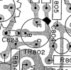
Looks like KSC2690 is the closest match. Pinout is different, but the legs on the board are configured in a triangle (rather than straight line), so should not be a problem putting those in.
nicholas2381
Super Member
Looks like that’ll do the trick.

Sui-Yogi
Super Member
Take a look here :
https://audiokarma.org/forums/index.php?threads/sansui-qs-100-update.974711/
all info about what is inside the IC’s and modules you can find it in the service bulletin of QS1 page 33 .
Imagine that in one of the modules there is a 2SC458; and some electrolytic capacitors , this should be all dead by now , including the bulb in the vactorls;
A significant improvement in the quadrophonic effect , when it comes to decode stereo to 4ch, is replacing the old vactrolls ( photocells ) , I don’t have quadrophonic material so I use the QS100 only in QS mode , I bought and sold the Involve SMv3 as in the QS ( involve ) mode ,it does the same job with the updated QS100 . I know its hard to believe but it’s true .
I suggest that you go ahead and rebuild all the modules/IC’s and get led vactrols for the photocells….. you will be surprised with the capabilities of this unit in QS .
Hope all goes well with your restoration!
https://audiokarma.org/forums/index.php?threads/sansui-qs-100-update.974711/
all info about what is inside the IC’s and modules you can find it in the service bulletin of QS1 page 33 .
Imagine that in one of the modules there is a 2SC458; and some electrolytic capacitors , this should be all dead by now , including the bulb in the vactorls;
A significant improvement in the quadrophonic effect , when it comes to decode stereo to 4ch, is replacing the old vactrolls ( photocells ) , I don’t have quadrophonic material so I use the QS100 only in QS mode , I bought and sold the Involve SMv3 as in the QS ( involve ) mode ,it does the same job with the updated QS100 . I know its hard to believe but it’s true .
I suggest that you go ahead and rebuild all the modules/IC’s and get led vactrols for the photocells….. you will be surprised with the capabilities of this unit in QS .
Hope all goes well with your restoration!
Last edited:
Take a look here :
https://audiokarma.org/forums/index.php?threads/sansui-qs-100-update.974711/
all info about what is inside the IC’s and modules you can find it in the service bulletin of QS1 page 33 .
Imagine that in one of the modules there is a 2SC458; and some electrolytic capacitors , this should be all dead by now , including the bulb in the vactorls;
A significant improvement in the quadrophonic effect , when it comes to decode stereo to 4ch, is replacing the old vactrolls ( photocells ) , I don’t have quadrophonic material so I use the QS100 only in QS mode , I bought and sold the Involve SMv3 as in the QS ( involve ) mode ,it does the same job with the updated QS100 . I know its hard to believe but it’s true .
I suggest that you go ahead and rebuild all the modules/IC’s and get led vactrols for the photocells….. you will be surprised with the capabilities of this unit in QS .
Hope all goes well with your restoration!
Thanks, Argou. i did follow your thread. Very interesting work. Is there one step you did that you think made a bigger difference over the others? Was the re-cap the biggest change, changing modules on F-1357, F-1356, other upgrades? I know you did these in sequence, so it may be hard to isolate the effect of individual changes alone.
I agree with your observations that the two "Hall" settings aren't really any different from each other or the "QS" mode with the boards in "original" state, so something clearly is amiss on the quad boards. It's clear the settings should have some difference in sound from Sansui literature for these units. The synthesizer mode is quite pleasing to my ears as is at this point.
Sui-Yogi
Super Member
Hello KeithD,
I hope you are moving forward with your restoration , I’m following with interest .
As you know I’m not a tech , so I’m actually waiting for someone who has knowledge about electronics to update/upgrade a similar or the same unit so they can explain to us what really happened there . Add to all this that my English sucks !
I would try to explain with simple words and how it’s in my head , hope it helps .
I would say with certainty that recapping the unit and placing film capacitors in the signal path made the biggest difference in sound quality ! The quadrophonic effect , I think is a different thing . The way that I hear it , is that nothing is happening at the frond speakers in term of separation, it’s just a stereo reproduction from the source as a normal stereo amplifier does , the game is at the rear speakers that produce that ambient sound , then all
4 channels are producing a sound stage in your listening space .
So if you want to bring up the capability of the unit producing this ambient sound for rear channels in addition of “clear” sound and separation you need to go through the Modules, IC’s and the photocells .
The photocells I think did the most big deference, if you ask me , almost equal was the rebuild of the modules/IC’s on the synthesiser board and last but not least the oscillator board .
Besides what I could hear , after replacing everything at the synthesiser board , I could see that even the VU meters for the rear channels was moving up and down individually rather than before that they were moving like it was a mono not stereo reproduction .
A tip I can give you , if you go down that road is that if you replace the Vactols be careful for the polarity of the LED . If you install it reverse (+ -) the transistor 2SC506 , in my case 2N3440 will start warming up fast , that will tell you that the polarity of the LED of the vactrol is incorrect , so I suggest keep your finger on the transistor when you tern on the unit .
Obviously I have no idea why this is happening, just letting you know .
I have seen your restoration threads in AK , I believe that this type of work would be a peace of cake for you and I’m sure you gonna make it look good too ( not like mine ) . The only little expensive component is the vactrols everything else is resistors , transistors and few film capacitors .
Hope I helped a bit !
Thank you for tolerating my English !!!
I hope you are moving forward with your restoration , I’m following with interest .
As you know I’m not a tech , so I’m actually waiting for someone who has knowledge about electronics to update/upgrade a similar or the same unit so they can explain to us what really happened there . Add to all this that my English sucks !
I would try to explain with simple words and how it’s in my head , hope it helps .
I would say with certainty that recapping the unit and placing film capacitors in the signal path made the biggest difference in sound quality ! The quadrophonic effect , I think is a different thing . The way that I hear it , is that nothing is happening at the frond speakers in term of separation, it’s just a stereo reproduction from the source as a normal stereo amplifier does , the game is at the rear speakers that produce that ambient sound , then all
4 channels are producing a sound stage in your listening space .
So if you want to bring up the capability of the unit producing this ambient sound for rear channels in addition of “clear” sound and separation you need to go through the Modules, IC’s and the photocells .
The photocells I think did the most big deference, if you ask me , almost equal was the rebuild of the modules/IC’s on the synthesiser board and last but not least the oscillator board .
Besides what I could hear , after replacing everything at the synthesiser board , I could see that even the VU meters for the rear channels was moving up and down individually rather than before that they were moving like it was a mono not stereo reproduction .
A tip I can give you , if you go down that road is that if you replace the Vactols be careful for the polarity of the LED . If you install it reverse (+ -) the transistor 2SC506 , in my case 2N3440 will start warming up fast , that will tell you that the polarity of the LED of the vactrol is incorrect , so I suggest keep your finger on the transistor when you tern on the unit .
Obviously I have no idea why this is happening, just letting you know .
I have seen your restoration threads in AK , I believe that this type of work would be a peace of cake for you and I’m sure you gonna make it look good too ( not like mine ) . The only little expensive component is the vactrols everything else is resistors , transistors and few film capacitors .
Hope I helped a bit !
Thank you for tolerating my English !!!
nicholas2381
Super Member

Hello KeithD,
I hope you are moving forward with your restoration , I’m following with interest .
As you know I’m not a tech , so I’m actually waiting for someone who has knowledge about electronics to update/upgrade a similar or the same unit so they can explain to us what really happened there . Add to all this that my English sucks !
I would try to explain with simple words and how it’s in my head , hope it helps .
I would say with certainty that recapping the unit and placing film capacitors in the signal path made the biggest difference in sound quality ! The quadrophonic effect , I think is a different thing . The way that I hear it , is that nothing is happening at the frond speakers in term of separation, it’s just a stereo reproduction from the source as a normal stereo amplifier does , the game is at the rear speakers that produce that ambient sound , then all
4 channels are producing a sound stage in your listening space .
So if you want to bring up the capability of the unit producing this ambient sound for rear channels in addition of “clear” sound and separation you need to go through the Modules, IC’s and the photocells .
The photocells I think did the most big deference, if you ask me , almost equal was the rebuild of the modules/IC’s on the synthesiser board and last but not least the oscillator board .
Besides what I could hear , after replacing everything at the synthesiser board , I could see that even the VU meters for the rear channels was moving up and down individually rather than before that they were moving like it was a mono not stereo reproduction .
A tip I can give you , if you go down that road is that if you replace the Vactols be careful for the polarity of the LED . If you install it reverse (+ -) the transistor 2SC506 , in my case 2N3440 will start warming up fast , that will tell you that the polarity of the LED of the vactrol is incorrect , so I suggest keep your finger on the transistor when you tern on the unit .
Obviously I have no idea why this is happening, just letting you know .
I have seen your restoration threads in AK , I believe that this type of work would be a peace of cake for you and I’m sure you gonna make it look good too ( not like mine ) . The only little expensive component is the vactrols everything else is resistors , transistors and few film capacitors .
Hope I helped a bit !
Thank you for tolerating my English !!!
Thanks for your insights, Argou, very helpful, and yes, your English is just fine!
My next steps on the 6500 are going to be replacing the large surface mount caps (which are the coupling caps and three PS caps), and then re-cap the tone board. Those are the ones that most affect the Sound Quality, I believe. After that, I will look at the quad boards and make sure I get film caps in the signal path on those. The next level would be re-doing the ICs as you have done. That's probably farther off in the future for me, but again, I greatly appreciate the insights and your positive comments on my other restorations. I've just completed work on an AU-777, and there is a noticeable improvement in SQ on that one after re-capping.
Replaced the PS and coupling caps with Nichicon LKG series. Somehow I got the diameter of C003 wrong, so the replacement was smaller than the bracket, but just used a bit of insulation foam to hold the new one in place.
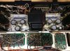
Measured old caps after removing them. These are all gray Elna. Capacitance was not bad, only one out of spec at 30% high. However, ESR seems high to me. I don't know what it should be, and I could not find ESR values for the LKG replacements. The old ones range from 38 to 230 Ω, which must be much higher than the new ones. Unfortunately, I did not measure the new ones before I put them in.
Parts on the way to recap the quad and tone boards.
Measured old caps after removing them. These are all gray Elna. Capacitance was not bad, only one out of spec at 30% high. However, ESR seems high to me. I don't know what it should be, and I could not find ESR values for the LKG replacements. The old ones range from 38 to 230 Ω, which must be much higher than the new ones. Unfortunately, I did not measure the new ones before I put them in.
Parts on the way to recap the quad and tone boards.
Had time to work on the quad boards last week. Here is the F-1372 stripped of e-caps. Boy, they did a nice job of clearly labeling everything on these boards, and no mistakes either!
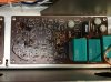
Used film caps for 10 µF values and less, Nichicon Fine Gold for larger values.
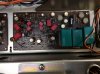
Then did the F-1371. Also replaced 2sc458 transistors.

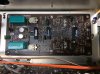
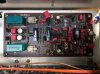
I have to say I have not noticed a difference in the quad processing. The Hall settings seem just a bit different from the Synthesizer setting, but not much. However, the static burst sound when shutting off the unit is now gone. I suspect that was the 2sc458s. Glad those are gone!
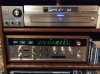
Here she is rotated back into my main quad listening system coupled with my QSD-2 so that I can switch back and forth between the QR processing and Vario-Matrix processing found in the QRX-9001 depending on what sounds better for the particular music I am listening to. I've got the cap replacements for the two tone boards, but decided to put that off for a future project. Using a Sony NC555ES for multichannel SACDs fed into the 4 channel AUX in of the QR-6500.
Used film caps for 10 µF values and less, Nichicon Fine Gold for larger values.
Then did the F-1371. Also replaced 2sc458 transistors.
I have to say I have not noticed a difference in the quad processing. The Hall settings seem just a bit different from the Synthesizer setting, but not much. However, the static burst sound when shutting off the unit is now gone. I suspect that was the 2sc458s. Glad those are gone!
Here she is rotated back into my main quad listening system coupled with my QSD-2 so that I can switch back and forth between the QR processing and Vario-Matrix processing found in the QRX-9001 depending on what sounds better for the particular music I am listening to. I've got the cap replacements for the two tone boards, but decided to put that off for a future project. Using a Sony NC555ES for multichannel SACDs fed into the 4 channel AUX in of the QR-6500.
nicholas2381
Super Member
Nice work!

matjo
Member
I'm building a list of components to replace in a QR-6500. I noticed there are oil caps on the list of "Other components" in the service manual:
C012 and 013 0.01 µF/400V
C014 0.033 µF/600V
C027 0.0047 µF/600V
C028 0.01/500V
I found C012 and C013 on the underside, each connected to a large diode.
View attachment 2561287
I've read these Suzuki oil caps tend to go bad, so first question is should I be replacing these, and if so, what are the replacements?
I've also replaced the 0.01/400V Suzuki oil caps; I measured them after replacing; I was surprised they were both within specs (even spot-on!).