• The move to the new server is done. There are some software and database maintenance updates in process. This has us passing the hat around to help out. We appreciate any donations. Seriously, even a dollar helps. The payment page may be found here - https://www.audiokarma.org/support.html

Question about FM antenna I made

H
Lightning?
Hopefully people are disconnecting their antennas during this time of year when they aren't home. It's the only protection, along with pulling the plug. Even a strike that's close enough can take out the front end of your tuner...especially with a gain antenna.
 
H

Hopefully people are disconnecting their antennas during this time of year when they aren't home. It's the only protection, along with pulling the plug. Even a strike that's close enough can take out the front end of your tuner...especially with a gain antenna.

Hopefully he grounded his new toy, or will now, because lighting doesn't care whether or not you're home. No, nothing is guaranteed, especially with a direct hit, but we mitigate what we can.
 
I'm always nervous about grounding also...there is such a thing as ground to cloud lightning. Nope..no guarantees. Direct hit will make you start looking at things that may be more important than the tuner. Fortunately, my antenna is generally pointed near where our heavy weather usually comes from and I can start to hear a little crackling in the signal. Radar app on the phone goes on next...looking for crazy colors...like last night.
 
I'm always nervous about grounding also...there is such a thing as ground to cloud lightning. Nope..no guarantees. Direct hit will make you start looking at things that may be more important than the tuner. Fortunately, my antenna is generally pointed near where our heavy weather usually comes from and I can start to hear a little crackling in the signal. Radar app on the phone goes on next...looking for crazy colors...like last night.

Living in the lightning capital of the country is why I've never had the balls to install an outside antenna.
 
Living in the lightning capital of the country is why I've never had the balls to install an outside antenna.
That's why I have 5 in my attic. 10 meter sloper dipole for ham use, discone for whatever I need it for, 6 element fm yagi &amplified dish for tv both on a rotator & an omni crossed fm dipole. Couple other ham antennae on poles on outbuildings.
 
Would a folded dipole have better reception than a single? I would say yes due to the larger area a folded would have but I don’t know crap as far as antennas go. This is a learning experience for me.
 
Would a folded dipole have better reception than a single? I would say yes due to the larger area a folded would have but I don’t know crap as far as antennas go. This is a learning experience for me.
Yes, more omnidirectional. A couple examples of commercially-available styles.
 

Attachments

  • 20200530_120407.jpg
    20200530_120407.jpg
    235 KB · Views: 27
Just got done changing out the phone wire for RG6 & it was a big improvement. Signal strength increased on most stations but not all & generally it sounds much better. Went to buy some twin lead wire but there wasn’t any but I did buy a transformer 75 - 300 ohm. I had to redo everything but I’m happy I did.
Thank all of y’all for your advice & info, it was very helpful!!!!
 
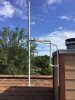
I’ll let the pictures do the talking. DC7A4968-A110-4F84-BF96-5BADB47938E1.jpeg AA66C271-B57E-43FE-94DB-43E3CBC74DDA.jpeg
I tried to soldered the fine wires to the antenna wire but couldn’t get it to solder, fine wires must be stainless. I used 10 ga.eye crimp on connectors,took off the yellow insulators, used my dremal to sand off the aluminum coating down to the copper. Used an awl to in large the crimp on portion to fit over the antenna wire. Slipped them on an soldered them on. Then #6 short screw & nut to connect both stainless & copper lead from RG6 to antenna wires Smeared clear silicone over it. Done... Pain in the ass to do but it’ll last.
 
Last edited:
I’ll let the pictures do the talking. View attachment 1883626 View attachment 1883627
I tried to soldered the fine wires to the antenna wire but couldn’t get it to solder, fine wires must be stainless. I used 10 ga.eye crimp on connectors,took off the yellow insulators, used my dremal to sand off the aluminum coating down to the copper. Used an awl to in large the crimp on portion to fit over the antenna wire. Slipped them on an soldered them on. Then #6 short screw & nut to connect both stainless & copper lead from RG6 to antenna wires Smeared clear silicone over it. Done... Pain in the ass to do but it’ll last.
The braid on RG-6 is aluminum...good luck getting solder to stick. Another thought is to use a chassis mount F jack...attach it through a small piece of plexiglass to mount it to you pole. Need a solder lug with an eyelet large enough to fit around the F connector barrel, so you can tighten the nut and make a secure ground connection. Then you can solder to the center pin and the ground lug and have better connections. And the folded dipole is basically a loop antenna. Loops will have a little more gain if you create more space inside the loop...square or circular shape will work. Circular is about the best compromise.
 
^^^on aluminum braid
If quad shield, 2 layers each of braid & alum.foil wrap. As long as it's weather proofed, good to go until it gets physically damaged (fat-ass bird, tree branch, wind, etc.)
 
Twin lead is pretty rare these days. The roll of basic twin lead I have I found at a long time local hardware store a few years ago. They probably had it on the shelf a long time and were probably glad to get rid of it.

I have built two cubical quads. They seem to work reasonably well and are pretty simple to build. Gain may be similar to folded dipole but seem far less sensitive to objects (including myself) near it than a folded dipole. Folded dipoles can be sensitive to things near its field.
IMG_20200530_212245.jpg
3/4 or 1/2 PVC pipe, 4 elbows, 1 tee
https://www.homedepot.com/p/OOK-25-ft-35-lb-18-Gauge-Copper-Hobby-Wire-50161/100152481
https://www.homedepot.com/p/Ideal-F-Series-Coaxial-Cable-Female-Adapters-2-Pack-85-071/204063261

Aim for the wire antenna inside to be just over 30 inches a side. With wire looped around inside can stick one end into middle of adapter and bend 90 degrees. Fits reasonably tight. Pull loose end tight and loop around outer end of adapter and solder. Can then use RG-6 to run to tuner. Can use white RTV to glue joints after it has been built. Put JB weld all over things on the inside to keep F adapter from pulling out and everything together. Looking to put this one in my attic if it will fit and I figure out a good way to run the lead down into my apartment. Have the material to make another for a friend to put in their attic. Supposed to be a 75 ohm design.
IMG_20200530_215007.jpg
 
Using the phone wire I’m picking up more fm stations now but the signal strength meter isn’t showing an improvement. I have the antenna in set horizontally, I’ll turn it vertically & see what happens. Don’t have any 300 ohm twin lead wire right now but I’ll get some.

I may have missed it if someone has already mentioned it. Your dipole is directional - bidirectional - not omnidirectional. Receive will be best broadside and diminished at the ends. If you can, try one of the weaker stations and slowly rotate the antenna and watch the S meter. Simple dipoles for FM can also suffer greatly from multipath which can severely diminish even a strong signal.

Good luck
 
Mounting a dipole vertically as in larry’s pics will have an omnidirectional receive pattern. I would have run the wire inside the pvc to protect it from the elements and those “fat-assed birds”. The use of larger diameter wire or tubing generally increases the usable bandwidth of an antenna.
Someone mentioned disconnecting outside antennas whenever you’re away. I live in an area of south La. that is second only to central Fl in lightning risk and I work in wireless communications. At one time I was responsible for inspecting grounding systems at our towers. Disconnecting an antenna may prevent the induced surge from a nearby strike, But a direct hit, which is no less likely if disconnected, can be dangerous and can cause a fire or kill someone. If you disconnected it and attached it to ground, that would direct the surge to ground. The problem without significant ground conductor is a direct hit to the antenna will probably destroy it and the small feeder line. If not grounded.
Most commercial installations use the same basic principles when protecting against lightning. First, the goal is directing the surge to earth, not preventing it. Those bristles on a stick and other doo-dads meant to mitigate the static build up during a storm are not effective and not used much professionally. On a tower, we ground the shield of the coax feeders to the tower near the antennas, then the shield is grounded near the base of the tower. The tower itself is grounded to a buried ground system. The coax shield is grounded again just before it enters the radio hut or cabinet. Just inside, surge arrestors are installed AND Grounded on the coax. This protects the center conductor of the coax. From this point back to the rf equipment, no more grounding of the feed line. Commercial AC mains is grounded to the same buries system and has what is called a whole building or whole house surge protector. This is a panel with various types of MOV’s banks of avalanche diodes, or gas discharge modules, or a combination of these. Most of the comms gear runs on DC and as such, it is well protected from AC surges due to the surge protector and DC power plant including large battery bank.
All connections to the outside world like ethernet, telephone, etc are also grounded at the building entrance. All significant metal such as doors, door frames, Eq racks, Etc are also ground. The ground leads never make sharp turns, always gradual turns in a downward direction. A surge, especially high energy, does not want to go up. Try to force that could result in arcing off the ground conductor.
The buried ground system consists of standard 8’ ground rods spaced 16’ apart (2xlength). The rods are cadweldelded or clamped to a solid tinned #2 wire that is also buried. Towers typically have one or two rods and a buried ring around them. That ring is connected to the building ground via one or more solid #2 wires also buried. The only exception are guy wire anchors. They are grounded with their own rods, but can be hundreds of feet away and not usually connected to the main ground system.
The equipment is grounded to a 24” large heavy copper bus bar. This bar will have a solid #2 tinned wire cadwelded to the bottome center edge. That goes directly to the buried ring outside. The bar has several holes for attaching wire terminals. One side, let’s say the left side, is where potential sources of Surge are attached such as the coaxial surge arrestors. The right side is the protected side and this is where the equipment grounds go. The theory here is that a surge hits theleft side of the bar and has to pass by the direct low impedance path to ground made by the large wire cadwelded to the center before it can reach the protected equipment side.
At every point, small things that direct the surge to ground combine to protect the RF gear very effectively. I know this sounds like over the top impractical solution for your FM antenna, but you can utilize many of the same principles. Most importantly:
1. All grounds are at the same potential andbonded to your mains ground. Don’t rely upon water pipes and such to accomplish this.
2. Bolt on clamps are fine outside if cadwelding is not an option. You just have to check it once in a while and retighten
3.Never rely upon solder in the ground path. Tinning wires is good. Solder can easily melt During a large surge.
4. We use solid #2 wires because it is durable. You can use smaller copper #6-8to bond ground rods and other connections.

5. bottom line is to have a single point ground that is at the same potential as the mains ground at your service entrance

6. Try to avoid stranded wire outdoors due to corrosion, never bury stranded insulated wire. Some people use wide copper straps to offer the lowest impedance at surge frequencies due to skin effect conductance- even more expensive.

On my ham station, i had a 25foot push up pole with several antennas on it. I had a single ground rod near the basewhich was next to my station. It had a wire clamped with bolted clamp that ran to my home ground rod, I had a wire attached with a pipe clamp around the base of the pole clamped to it( downward direction) and a piece of aluminum with bulkhead so239’ s for each antenna. This aluminum bar was mounted to the wall close to the earth and served the purpose of grounding the shields on the coax cables before entering the shack. It was close to the ground ( the physical ground, but also near the rod) so any high intensity surges would tend to go directly to ground. I only had two polyphaser surge protectors out of 4 antennas - 5 including a long wire in the trees. I had a small copper busbar setup the same as described earlier and grounded all equipment to it in the method described. The ARRL used to recommend a piece of copper pipe used as a bus bar in the same manner. My system with mixed metals and smaller conductors was not as effective as the commercial installations, but more effective than most. My point is it isn’t all or nothing. You can have effective grounding on a budget.

 
Damn i can sure be pretty wordy at times
After reading your long reply on grounding I made a grounding stake. I have a 44 in. iron stake that is 7/8 dia. I also have several pieces of 7/8 copper tubing but there all about 10 ins. long & slightly bent. I hammered them into the stake & soldered them together. I know it’s not long enough, 3’ 6” but something is better than nothing. I have a brass grounding clamp also & enough 10 ga. stranded wire,not perfect but it’ll have to do. Question is if I connect the ground to the antenna will it have a negative effect on the reception? Thanks for any info!
 
Now that I’ve a a caffeine fix I do have have enough RG6 with a grounding wire, used on a WiFi dish.
 
Last edited:
Back
Top Bottom