• The move to the new server is done. There are some software and database maintenance updates in process. This has us passing the hat around to help out. We appreciate any donations. Seriously, even a dollar helps. The payment page may be found here - https://www.audiokarma.org/support.html

Questions Regarding Pioneer SX-680 Problems: It all started with buzzing

RogerALB

New Member
I acquired a Pioneer SX-680 that needs TLC, and I figured it would be a good opportunity to learn some new stuff. The situation started with a loud buzz from the speakers. I think there may be more than one problem.

In the process of diagnosing the buzz I discovered that R401 was dead. I replaced it. Today I found out that R341 (the PC Board Connection Diagram is hard to read, but it is 2.2ko 1/2w connected to the 4a fuse near point 9) is also dead.

The outgoing low voltage leads on the power supply transformer are pins 11 & 12 36.7v, pin 14 24.5v.

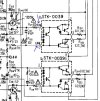
The voltages for the SSTK0039 units are a bit nutty with pin 1 24.2v on the left and 25.2 on the right; pin 34.2 on the left and right; pin 3 26.8 left and 26.4 right; pin 8 26.9 left and 26.5 right; pin 9 26.9 both sides; pin 10 26.9 left and 27.6 right. My understanding is that some of those voltages are waaaaaaaaaaaaaaaaaaaay out of spec.

But, what is really spooky is that I am getting 108v on both sides of R401 and at various points as I track the traces and so on. Obviously, this is not remotely correct.

My most recent thinking is that there is a voltage "leak" (call it a short if you wish) on the incoming side of the power supply transformer. I thought R341 (or whatever it is) might be the culprit, but I don't know. Then I thought that maybe the STK0039 units were bad (which I guess they are) and causing some sort of voltage irregularity.

Anyway, I am tracking and tracing and having a rollicking good time, too. Not really, but it is interesting.

Does anybody have a few ideas about what might be going on with this SX-680?

Thanks for considering.

RogerALB
 
Register to hide this ad
Test D401 and D402 you will need to lift one end of them to test.
Well, I tested, retested, and then tested again because it seemed like a good idea. The good news is that the diodes are good. The bad news is that the diodes were not the problem.

I must put on my thinking cap and get back at it.

Thanks!
 
UPDATE: OK, I think I have the voltage situation (108v) sorted out. Suffice it to say, much fiddling and testing, but all seems to be good.

The buzzing is still buzzing so I am going to deal with the STK0039 situation.

I have replaced a couple of bum resistors, so I am pleased.

Will update and look forward to comments.

Again, many thanks!
 
UPDATE: OK, I think I have the voltage situation (108v) sorted out. Suffice it to say, much fiddling and testing, but all seems to be good.

The buzzing is still buzzing so I am going to deal with the STK0039 situation.

I have replaced a couple of bum resistors, so I am pleased.

Will update and look forward to comments.

Again, many thanks!
:thumbsup:

I think it is always nice to let us know what you found that fixed part of or all of the problem.

It may help someone else in the future if they have the same issue and search for a buzzing SX-680.
 
:thumbsup:

I think it is always nice to let us know what you found that fixed part of or all of the problem.

It may help someone else in the future if they have the same issue and search for a buzzing SX-680.
I was hoping that is the case. I know that I am always pleased to find out how things turn out.

I will know more in a few days when I get the STK0039 units installed. I will post another update then.
 
Well, I tested, retested, and then tested again because it seemed like a good idea. The good news is that the diodes are good. The bad news is that the diodes were not the problem.

I must put on my thinking cap and get back at it.

Thanks!
Another Update:

Failure!!!

I swapped the STK0039 modules and here's the current situation:
  • When the power is turned on (but the speakers are off) the meters on the front panel go to a little past "1", that is, a bit over straight up.
    • The panel and meter lights are on.
    • The dim bulb is off.
  • When the speakers are turned on, the buzz remains on the right channel.
    • The meters drop to "0".
    • The panel lights and the meter lights go off.
    • The dim bulb goes to full bright.
  • With the power on and the speakers off the VDC at the STK0039 pins remain as before, that is, way off.
I was put my replacement of the main panel capacitors, etc. on hold until I swapped out the modules. Now that the swap has been done I think I will finish the swapping. I am trying to sort out my logic on the problem, and I am baffled.

Needless to say, comments and ideas are welcome!

R
 
Another Update:

Failure!!!

I swapped the STK0039 modules and here's the current situation:
  • When the power is turned on (but the speakers are off) the meters on the front panel go to a little past "1", that is, a bit over straight up.
    • The panel and meter lights are on.
    • The dim bulb is off.
  • When the speakers are turned on, the buzz remains on the right channel.
    • The meters drop to "0".
    • The panel lights and the meter lights go off.
    • The dim bulb goes to full bright.
  • With the power on and the speakers off the VDC at the STK0039 pins remain as before, that is, way off.
I was put my replacement of the main panel capacitors, etc. on hold until I swapped out the modules. Now that the swap has been done I think I will finish the swapping. I am trying to sort out my logic on the problem, and I am baffled.

Needless to say, comments and ideas are welcome!

R
Update to the Update:

When I disconnected the speakers and pressed the speaker selection button nothing bad happened. The lights stayed on, etc.
When I plugged in headphones there was buzzing in both sides of the 'phones.

That's it for now.
 
Update to the Update of the Update:

OK, enough of the update mania, I think we all get it, but I was on a roll, and, you know how that goes.

The situation here is now a little different. I have been installing capacitors and such from one of those update kits, and it is slow going but educational.

But I ended up with the buzz being in the right channel only. Might be progress, or not. Maybe I made a mistake originally and the buzz was on the right side only from the start of this. Maybe I am second guessing myself. Nevertheless, it was buzzing on the right.

I one cap is a little hard to find, C335, but I found it and swapped it. At the same time, I discovered a faulty soldering job on one of the main power capacitors (my fault) so I fixed that.

Now things are better but not fixed.

Here is the current status:

  • With the power ON and the speakers OFF and an input to AUX -
    • The panel lights are on
    • The dim bulb is off
    • The meters are operating to match the signal from the AUX, including variations based on the volume control, more volume means more needle wig-wagging
    • The green SOURCE light is on
  • With the power ON and the speakers ON and an input to AUX -
    • The panel lights are off
    • The dim bulb is full on
    • The meters immediately "crash" to the far left, what I call the "off" position
    • The green SOURCE light is off
    • There is a hum on the right channel
      • This seems to dissipate after a few moments, but I hesitate to investigate more as I do not want to risk damage to parts
      • There is no sound from the stuff coming in from AUX
My current thinking is that there is either a short of a ground problem on between the STK modules and the speaker connections. There is a lot of circuitry there, so there's a ton of possibilities.

I have made a very nice enlargement that's 3' wide of the circuitry schematic, and that sure helps. I made a slightly smaller one of the P. C. Board Connection Diagram, too.

Comments and ideas are welcome.

R
 
I think the STKs are toast (i have seen them humming when speakers connected). Also you shouldnt be playing music in DBT as DBT could be strangling the power available to the amp
 
I think the STKs are toast (i have seen them humming when speakers connected). Also you shouldnt be playing music in DBT as DBT could be strangling the power available to the amp
You note about the dim bulb tester is very important. Using a bulb with a lower wattage than the device plugged into it will almost certainly strangle the power as you describe. Anybody using such a thing should make note of this.

In this case the SX-680 is listed at 95w so I am using a 100w bulb. This gives a small about of "headroom" yet still provides protection to avoid a "runaway" draw.

The humming is on the right channel. With that in mind, swapping the STK modules left-to-right should cause the hum to change channels, too, if the problem is with one of the modules. Unfortunately, in this case that turns out to be too easy and the hum stays on the right channel.

The other clue is that the meters work nicely in such a way that it appears there is a satisfactory signal on both channels. Because the meters are "downstream" of the modules (not exactly correct but close enough for this discussion) it would seem that the problem is "beyond" the meters. Pardon the quotation marks, but I am describing the situation in rather loose terms.

So, my puzzle of the moment is a) whether or not I am correct in my understanding of the signal path, and b) can I find the problem?

If I am wrong about "a", what is my alternative, and thus "b" become what can I do about that?

The story continues. It is all highly educational.
 
Can you clarify something please?

With the power ON and the speakers ON and an input to AUX -
  • The panel lights are off
  • The dim bulb is full on
  • The meters immediately "crash" to the far left, what I call the "off" position
  • The green SOURCE light is off
  • There is a hum on the right channel
    • This seems to dissipate after a few moments, but I hesitate to investigate more as I do not want to risk damage to parts
    • There is no sound from the stuff coming in from AUX
These are kind of rambling thoughts on your situation.

I'm assuming you have speakers or a dummy load hooked up?

When you turn the speakers on is the volume control turned up at all?

Does this happen with both the A & B speaker switches?

There is no sound from the aux? Does that mean you have sound from some other source(s)?

Have you tried listening with headphones? (speaker switch off) The headphone circuit is before the speaker switch.

It is typically OK to listen to phones with the DBT hooked up.
With the series resistors in the headphone circuit you will not be drawing much power out the amp.

If the DBT bulb is not voltage starving the unit then I find it very strange that all the lights go out. On the other hand with a full bright bulb they could be voltage starved.

Have you checked the power supply circuit voltages, there are a couple that you should have a look at.

Check them with the speaker switch off, I'm sure they take a dive with the DBT bright, especially the minus 33.

Also confirm the value of R410.

680ps1.jpg
 
Can you clarify something please?


These are kind of rambling thoughts on your situation.

I'm assuming you have speakers or a dummy load hooked up?

When you turn the speakers on is the volume control turned up at all?

Does this happen with both the A & B speaker switches?

There is no sound from the aux? Does that mean you have sound from some other source(s)?

Have you tried listening with headphones? (speaker switch off) The headphone circuit is before the speaker switch.

It is typically OK to listen to phones with the DBT hooked up.
With the series resistors in the headphone circuit you will not be drawing much power out the amp.

If the DBT bulb is not voltage starving the unit then I find it very strange that all the lights go out. On the other hand with a full bright bulb they could be voltage starved.

Have you checked the power supply circuit voltages, there are a couple that you should have a look at.

Check them with the speaker switch off, I'm sure they take a dive with the DBT bright, especially the minus 33.

Also confirm the value of R410.

View attachment 3613356
These are kind of rambling thoughts on your situation.
Rambling thoughts are better than no thoughts at all!

I'm assuming you have speakers or a dummy load hooked up?
Correct. 8ohm speakers.

When you turn the speakers on is the volume control turned up at all?
Yes. When the volume knob is at 0 the front panel meters have no reaction. As the volume knob goes up the meters react accordingly.

Does this happen with both the A & B speaker switches?
Yes, both A & B switches. Appears to be identical.

There is no sound from the aux? Does that mean you have sound from some other source(s)?
No sound from AUX, TAPE 1, TAPE 2, AM, or FM. I have not checked PHONO.

Have you tried listening with headphones? (speaker switch off) The headphone circuit is before the speaker switch.
Yes! Sound from headphones, but very, very crackly. Volume reacts to changes by volume knob. Note that this is actually a change as I had hum in the headphones a couple of days ago.

It is typically OK to listen to phones with the DBT hooked up.
With the series resistors in the headphone circuit you will not be drawing much power out the amp.
OK, makes sense. That is what I did.

If the DBT bulb is not voltage starving the unit then I find it very strange that all the lights go out. On the other hand with a full bright bulb they could be voltage starved.
When the speakers go on, the DBT bulb goes bright and the panel lights and meters out. In other types of systems (I have experience in theatrical lighting) this often indicates a short or short-like problem. I don’t like to transfer past experiences to current situation, so I am “just sayin’”.

Have you checked the power supply circuit voltages, there are a couple that you should have a look at.
Yes, at pins 12 & 11 I have 36.8v
At Pins 15 & 15 there’s 24.5v

Near R410 (as per the diagram) I have 33.8v
Near the transistor shown by the top arrow on your diagram I have 46v


Check them with the speaker switch off, I'm sure they take a dive with the DBT bright, especially the minus 33.
Done, for sure.

Also confirm the value of R410.
R410 is 100ohm
Confirmed, it is original and correct. I double checked the color value bands.

Your ideas and comments are very much appreciated!!

RogerALB
 
There is no sound from the aux? Does that mean you have sound from some other source(s)?
No sound from AUX, TAPE 1, TAPE 2, AM, or FM. I have not checked PHONO.
That may be somewhat telling and a bit confusing as well.

You said earlier:

The other clue is that the meters work nicely in such a way that it appears there is a satisfactory signal on both channels. Because the meters are "downstream" of the modules (not exactly correct but close enough for this discussion) it would seem that the problem is "beyond" the meters. Pardon the quotation marks, but I am describing the situation in rather loose terms.
What is making the meters work if you have no signal. The meters are in line from the same place as the headphones, just before the speaker switches.


With the speakers off does it look like the FM tuner is working, meter moving, stereo light coming on?

If FM seems to be working and you have another amp take a record output from the 680 to an aux input on the other amp and see if the sources (AM/FM/AUX) on the 680 are working. If they do it eliminates a bunch of stuff before the 680 volume control.
 
In order to help us help you it is important to designate voltages, and sometimes the reference point. (typically ground)

I think most of us will assume that if somebody writes 12 volts that it is a positive DC voltage.

What if the place in the circuit is AC or a negative DC voltage, we need to designate that.

I think we also will mostly assume that the same 12 volts is measured with ground as the reference.

What if you were measuring from one pin to another? Helps to know that too.


My question to you was. "Have you checked the power supply circuit voltages, there are a couple that you should have a look at."
Yes, at pins 12 & 11 I have 36.8v
At Pins 15 & 15 there’s 24.5v

Near R410 (as per the diagram) I have 33.8v
Near the transistor shown by the top arrow on your diagram I have 46v

Pins 11 and 12 That should be noted as vac Pin 11 = 36.8vac and pin 12 = 36.8vac

Was it measured from pin 11 to pin 12, or from pin 11 to ground and pin 12 to ground.

If you measured pin to pin the voltage would be double

Same thing for pins 14 and 15. pin to pin or pin to ground? Noted as vac

I think that you measured to ground not pin to pin. That is what I typically assume folks do but remember unless you post pictures or are very explicit we don't know what you did.

I also typically assume we are measuring DC voltage but if not be clear about it.

I do hope that you measured -33.8 vdc not 33.8 (which implies +) near R410.

Here is an example of where polarity designation really matters.

680 ps2.jpg

You don't need to do it again, just remember to designate if not + or not a DC voltage.

Seems like the power supplies are where they should be as long as the speakers are not on.
 
Can you clarify something please?


These are kind of rambling thoughts on your situation.

I'm assuming you have speakers or a dummy load hooked up?

When you turn the speakers on is the volume control turned up at all?

Does this happen with both the A & B speaker switches?

There is no sound from the aux? Does that mean you have sound from some other source(s)?

Have you tried listening with headphones? (speaker switch off) The headphone circuit is before the speaker switch.

It is typically OK to listen to phones with the DBT hooked up.
With the series resistors in the headphone circuit you will not be drawing much power out the amp.

If the DBT bulb is not voltage starving the unit then I find it very strange that all the lights go out. On the other hand with a full bright bulb they could be voltage starved.

Have you checked the power supply circuit voltages, there are a couple that you should have a look at.

Check them with the speaker switch off, I'm sure they take a dive with the DBT bright, especially the minus 33.

Also confirm the value of R410.

View attachment 3613356
These are kind of rambling thoughts on your situation.
Rambling thoughts are better than no thoughts at all!

I'm assuming you have speakers or a dummy load hooked up?
Correct. 8ohm speakers.

When you turn the speakers on is the volume control turned up at all?
Yes. When the volume knob is at 0 the front panel meters have no reaction. As the volume knob goes up the meters react accordingly.

Does this happen with both the A & B speaker switches?
Yes, both A & B switches. Appears to be identical.

There is no sound from the aux? Does that mean you have sound from some other source(s)?
No sound from AUX, TAPE 1, TAPE 2, AM, or FM. I have not checked PHONO.

Have you tried listening with headphones? (speaker switch off) The headphone circuit is before the speaker switch.
Yes! Sound from headphones, but very, very crackly. Volume reacts to changes by volume knob. Note that this is actually a change as I had hum in the headphones a couple of days ago.

It is typically OK to listen to phones with the DBT hooked up.
With the series resistors in the headphone circuit you will not be drawing much power out the amp.
OK, makes sense. That is what I did.

If the DBT bulb is not voltage starving the unit then I find it very strange that all the lights go out. On the other hand with a full bright bulb they could be voltage starved.
When the speakers go on, the DBT bulb goes bright and the panel lights and meters out. In other types of systems (I have experience in theatrical lighting) this often indicates a short or short-like problem. I don’t like to transfer past experiences to current situation, so I am “just sayin’”.

Have you checked the power supply circuit voltages, there are a couple that you should have a look at.
Yes, at pins 12 & 11 I have 36.8v
At Pins 15 & 15 there’s 24.5v

Near R410 (as per the diagram) I have 33.8v
Near the transistor shown by the top arrow on your diagram I have 46v


Check them with the speaker switch off, I'm sure they take a dive with the DBT bright, especially the minus 33.
Done, for sure.

Also confirm the value of R410.
R410 is 100ohm
Confirmed, it is original and correct.

Your ideas and comments are very much appreciated!!

RogerALB

In order to help us help you it is important to designate voltages, and sometimes the reference point. (typically ground)

I think most of us will assume that if somebody writes 12 volts that it is a positive DC voltage.

What if the place in the circuit is AC or a negative DC voltage, we need to designate that.

I think we also will mostly assume that the same 12 volts is measured with ground as the reference.

What if you were measuring from one pin to another? Helps to know that too.


My question to you was. "Have you checked the power supply circuit voltages, there are a couple that you should have a look at."


Pins 11 and 12 That should be noted as vac Pin 11 = 36.8vac and pin 12 = 36.8vac

Was it measured from pin 11 to pin 12, or from pin 11 to ground and pin 12 to ground.

If you measured pin to pin the voltage would be double

Same thing for pins 14 and 15. pin to pin or pin to ground? Noted as vac

I think that you measured to ground not pin to pin. That is what I typically assume folks do but remember unless you post pictures or are very explicit we don't know what you did.

I also typically assume we are measuring DC voltage but if not be clear about it.

I do hope that you measured -33.8 vdc not 33.8 (which implies +) near R410.

Here is an example of where polarity designation really matters.

View attachment 3613480

You don't need to do it again, just remember to designate if not + or not a DC voltage.

Seems like the power supplies are where they should be as long as the speakers are not on.
Good points! I should have specified the gory details.

Yes, pins 11,12, 14, and 15 were measured pin to ground VAC. I learned about the doubling a few days ago and spent too much time scratching my head over the issue. Thanks for the follow-up on that.

Again, yes, the other voltages were DC and now I am worried about the + or - voltage near R410! I will check ......... -33.9VDC (I ran away and checked) to ground, by the way.

Your schematic, above, showing the voltages on the STK modules is concerning. I double checked (actually, quadruple checked) and my readings are not good.

I am about ready to have a fit. Here are my readings (and I hope I am wrong):

Left module - Pin 1, 33vdc, pin 2 -33.9vdc, pin 3 33.5vdc pin 8 33.5vdc, pin 9 33.7 vdc, pin 10 34.4 vdc measured pin to ground.

Right module is nearly exactly the same. My info is radically different. Not to mention what is on the schematics.

Should I go into panic mode here? What the heck!

Your help is appreciated, for sure.

Thanks.

Roger ALB
 
That may be somewhat telling and a bit confusing as well.

You said earlier:


What is making the meters work if you have no signal. The meters are in line from the same place as the headphones, just before the speaker switches.


With the speakers off does it look like the FM tuner is working, meter moving, stereo light coming on?

If FM seems to be working and you have another amp take a record output from the 680 to an aux input on the other amp and see if the sources (AM/FM/AUX) on the 680 are working. If they do it eliminates a bunch of stuff before the 680 volume control.
The FM meter does not work and the stereo light is not on.

Yes, this is confusing to the max. I am using this as a learning experience. But, I may end up making it a multi-part TV mystery. Probably on the Hallmark channel. Or not.
 
The FM meter does not work and the stereo light is not on.

Yes, this is confusing to the max. I am using this as a learning experience. But, I may end up making it a multi-part TV mystery. Probably on the Hallmark channel. Or not.
Never fear over time things will slowly start to make sense, or your brain will explode and then it will all magically fall into place. :biggrin:

Let's have a look at the FM right now. The AM and FM section is powered by the +13 volt supply.

Check the blue point for +13.6 volts if it is not there step back to the red point for +30 and if still missing check the far right side (on the diagram) of R402.
If the voltage is there then check R402 for open. If open ask why would it open? Resistors usually open up because they have too much current pulled through them.

If C405 shorts then you have the full 34.5 volts going through it to ground, poof. There could be a short or low resistance in the circuits on the emitter side of Q401 drawing too much current, or some other reason TBD.

680fmps.jpg


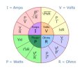
Ohms law for fun if C405 shorted out R407 would have the full +34.5 volts going through it back to ground (shorted cap). I=V/R
That would draw 734mA causing the resistor to dissipate 25 Watts of power, won't last long like that.
:yikes:
P=V*I

Ohms Law Pie Chart.jpg
 
Never fear over time things will slowly start to make sense, or your brain will explode and then it will all magically fall into place. :biggrin:

Let's have a look at the FM right now. The AM and FM section is powered by the +13 volt supply.

Check the blue point for +13.6 volts if it is not there step back to the red point for +30 and if still missing check the far right side (on the diagram) of R402.
If the voltage is there then check R402 for open. If open ask why would it open? Resistors usually open up because they have too much current pulled through them.

If C405 shorts then you have the full 34.5 volts going through it to ground, poof. There could be a short or low resistance in the circuits on the emitter side of Q401 drawing too much current, or some other reason TBD.

View attachment 3613559


Ohms law for fun if C405 shorted out R407 would have the full +34.5 volts going through it back to ground (shorted cap). I=V/R
That would draw 734mA causing the resistor to dissipate 25 Watts of power, won't last long like that.
:yikes:
P=V*I

View attachment 3613585
Well, I checked the 13.5VDC at the point indicated and it matched nicely. While I was at it I checked for the 30VDC at the red point and it was good, too. Both were point to ground.

I did change C405 the other day, as a matter of fact, so it is fresh as a daisy. I checked it again just now and it is the right one in the right place put in the right way.

RogerALB
 
Back
Top Bottom