
• The move to the new server is done. There are some software and database maintenance updates in process. This has us passing the hat around to help out. We appreciate any donations. Seriously, even a dollar helps. The payment page may be found here - https://www.audiokarma.org/support.html

Realistic receiver amp circuit analysis comparison attempt (STA-77 vs QTA-753)

VA1DER

Member
I have been doing some refurbishing of old Realistic receivers and trying to analyze some amplifier finals of the day. It started when I was really impressed with the sound quality coming from an old STA-77. I'm trying to get a feel for exactly what everything is doing. Here is it's main amp:
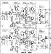
sta77_final.png

I've included left and right because they are subtly different around R615 and R616, likely a drafting error on one of them but I don't have my STA-77 at the moment and can't check which one is true.
So, here's what I've identified myself:
  • Differential pair TR601 and TR602 act as input stage - one side of the differential input is tied to ground, so this basically acts as a first stage and phase splitter all in one. Still gives good common mode rejection and good isolation.
  • TR607 and TR609 a fully complementary NPN/PNP pair for the second stage
  • TR611 and TR613 are two NPN power transistors operating semi-complementary.
  • TR615 Feedback for overload detection and suppression
Questions:
  • TR605 - a cascode transistor? It's not wired quite the way I would expect a cascode to be to a differential pair, but I'm still learning this topology. Improving isolation? Some sort of bias set point? I'm not really sure here.
  • Dual diode D601 and D611/VR601 appear to be a Baxandall diode sort of setup, but they are on the inputs of the second stage - I would typically see a Baxandall diode on the base of one of the NPNs, but I suppose putting it on the second stage could work too - that makes VR601 an adjustment for reducing crossover distortion? Am I misreading this?
Despite my questions, overall I'm quite impressed with this design in a 1975 receiver. It seems quite sophisticated. And I love the sound that comes from this receiver. Just beautiful.

Then I came across a QTA-753 for a great price - it's on its way as I write this. I pictured the QTA-753 the way it was marketed, as the quadraphonic "big brother" - the four-channel clean (vice Haffler circuit) version of the STA-77. But looking at the schematic for it, it impresses me a lot less. This main amp is very different architecture:
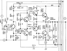
hfe_realistic_qta-753_schematic_finalamp.png

This seems far less sophisticated. This is what I've identified:
  • TR601 = input transistor operating class A with the 17V bias, voltage amp first stage
  • TR603 = phase splitter for the second stage, with VR901 providing crossover point tweaking
  • TR604 and TR605 - Fully complementary PNP/NPN second stage
  • TR606 and TR607 - Quasi-complementary NPN finals
Questions:
  • D601/D602 - Baxandall diode? But why two and why is one bussed with the D602 of every other channel?
  • Is there anything in this providing the kind of overload protection in the STA-77's main amp?
  • Is there anything in this providing the same kind of common-mode rejection in the STA-77's main amp?
It's not a terrible circuit from what I can make out, but it doesn't seem to be anything to write home about.

Anyway, I'd love comments and corrections to anything I've misidentified here.

EDIT: So far these are the features I've identified in each circuit. Please comment if there is anything I've missed or mis-identified.

STA-77QTA-753
Info▪1976 (STA-76 with likely same design was 1975)
▪$299 new
▪Stereo with Haffler pseudo-quad
▪"16W" per channel
▪1975
▪$339 new
▪Four-channel clean with ability to link channels for higher power
▪"15W" per channel quad, "32W" per channel stereomax
Baxandall compensation
✅
✅
Crossover point tweaking
✅
✅
Temperature compensation
✅
❌️​
Common-mode rejection
✅
❌️​
Soft-clipping/overload
✅
❌️​
 
Last edited:
Register to hide this ad
I have been doing some refurbishing of old Realistic receivers and trying to analyze some amplifier finals of the day. It started when I was really impressed with the sound quality coming from an old STA-77. I'm trying to get a feel for exactly what everything is doing. Here is it's main amp:
View attachment 3670229

I've included left and right because they are subtly different around R615 and R616, likely a drafting error on one of them but I don't have my STA-77 at the moment and can't check which one is true.
So, here's what I've identified myself:
  • Differential pair TR601 and TR602 act as input stage - one side of the differential input is tied to ground, so this basically acts as a first stage and phase splitter all in one. Still gives good common mode rejection and good isolation.
  • TR607 and TR609 a fully complementary NPN/PNP pair for the second stage
  • TR611 and TR613 are two NPN power transistors operating semi-complementary.
  • TR615 Feedback for overload detection and suppression
Questions:
  • TR605 - a cascode transistor? It's not wired quite the way I would expect a cascode to be to a differential pair, but I'm still learning this topology. Improving isolation? Some sort of bias set point? I'm not really sure here.
  • Dual diode D601 and D611/VR601 appear to be a Baxandall diode sort of setup, but they are on the inputs of the second stage - I would typically see a Baxandall diode on the base of one of the NPNs, but I suppose putting it on the second stage could work too - that makes VR601 an adjustment for reducing crossover distortion? Am I misreading this?
Despite my questions, overall I'm quite impressed with this design in a 1975 receiver. It seems quite sophisticated. And I love the sound that comes from this receiver. Just beautiful.

Then I came across a QTA-753 for a great price - it's on its way as I write this. I pictured the QTA-753 the way it was marketed, as the quadraphonic "big brother" - the four-channel clean (vice Haffler circuit) version of the STA-77. But looking at the schematic for it, it impresses me a lot less. This main amp is very different architecture:

View attachment 3670248

This seems far less sophisticated. This is what I've identified:
  • TR601 = input transistor operating class A with the 17V bias, voltage amp first stage
  • TR603 = phase splitter for the second stage, with VR901 providing crossover point tweaking
  • TR604 and TR605 - Fully complementary PNP/NPN second stage
  • TR606 and TR607 - Quasi-complementary NPN finals
Questions:
  • D601/D602 - Baxandall diode? But why two and why is one bussed with the D602 of every other channel?
  • Is there anything in this providing the kind of overload protection in the STA-77's main amp?
  • Is there anything in this providing the same kind of common-mode rejection in the STA-77's main amp?
It's not a terrible circuit from what I can make out, but it doesn't seem to be anything to write home about.

Anyway, I'd love comments and corrections to anything I've misidentified here.

Dual diode D601 and D611/VR601 appear to be a Baxandall diode sort of setup, but they are on the inputs of the second stage
This looks like the bias circuit for the output, the dual diode provides a fixed bias, not sure what D612 is doing as usually there is not a diode across the variable resistor, which is generally used for setting the bias-could be wrong on this
 
I've found some of these receiver ls used fixed resistors for bias and DC offset.
The only two trimmers usually found on the various receivers and amp boards are voltage balance controls for each channel I believe. I saw that described as such in one of the sercivice manuals, and even listed as such in the parts list.
 
This looks like the bias circuit for the output, the dual diode provides a fixed bias, not sure what D612 is doing as usually there is not a diode across the variable resistor, which is generally used for setting the bias-could be wrong on this

I have now seen a reference to Baxandall diodes being applied to the base of the driver transistor, and not just to one of the NPN pair directly. So I think D601 & D611/VR601 in the STA-77 amplifier have multiple purposes.
  • The signal is split into normal and inverted by this point, so I think you're right these are bias, but act to set the crossover point bias
  • Diodes are also used both top and bottom for temperature compensation, but...
  • Two diodes are on one and one on the other to provide a Baxandall-type compensation for one side.
  • The trimmer allows crossover point tweaking.
If this works as I suspect, it just reinforces my appreciation for the STA-77 design.

There is another thread talking about the STA-90 final amplifier, and how it contributes to that receiver's particularly good sound. The STA-77 design looks very much like it.
 
Last edited:
Back
Top Bottom