• The move to the new server is done. There are some software and database maintenance updates in process. This has us passing the hat around to help out. We appreciate any donations. Seriously, even a dollar helps. The payment page may be found here - https://www.audiokarma.org/support.html

Recap parts list for an MX-110 Z??

I do appreciate the guidance. Been out of touch the last week or so due to my job, or lack thereof come January so I apologize.
On a positive note, stopped by a fellow AK-ers house and as luck would have it he had an L-52 cab that he wasn't fond of and ... I was. So after some glass and trim detail, here's a pic. It sounds wonderful and looks the same. :)
IMG_3636.jpg

May I ask what lamps you are using? I replaced mine and they are still so dim. The slider is at bright as well.
 
Bit of an old thread, but I'll try and contribute....

Have my 110Z upstairs upside down on my bench. Finally have collected the nerve to work on this valuable piece of gear....

Schematics with handy notations from dshoaf (Thanks again Dave!)

CIMG7076.jpg


The smoking gun(cap)?

CIMG7073.jpg


AHA!...the plot thickens....

CIMG7075.jpg


The basic raw material....I know it's been to a local tech, and it seems he added that additional PS cap. But, that's only a patch in my mind....:thumbsdn:

CIMG7074.jpg


I couldn't find any voltage values on many of the caps or on the schematic or parts list, but the earlier info on this thread has answered at least one question. I have some nice Sprague Vit Q's and 118P's that have been begging for an application, but they are only 200 V rated caps. I see that they sould work just fine around the 12AX7's, since the highest voltages in that location are safely under 200V. And I also have lots of those lemon drops among others for the micas and ceramics.

One quick question. Where would I gain the most benefit from using pricier/fancier/boutique caps?

TIA.......:thmbsp:
 
For sure, get rid of those 2 bumble bees on the 12ax7 and replace the ceramic caps on the 6d10. In front of the 12ax7, there are a couple of 1µf 'lytic axial caps that can be replaced with film caps.

Probably, a lot of this has already been addressed in the earlier posts but I ain't going back and reading 4 pages. :D

Murray
 
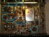
AA, I took your picture and added the places where the caps need attention. I know I put them on the schematic for you but this should help others, too. With a bit of time most anyone should be able to see what cap goes where on the drawings.

The ones in blue are the areas where you'll need to focus. The ones in red, leave alone until you're happy with the performance and the operating voltages are in spec.

I _did not_ mark the high voltage filter caps that oboviously need swapping out. I _did_ mark the low voltage filter cap in the lower corner as it, too, is leaking.

Lastly, I normally install a CL-90 thermistor inline with the AC line. The most convenient point for that is to remove the jumper wire from the back end of the fuse holder over to the AC socket. Use some tubing on the exposed legs for safety when it is installed. I generally install it so that the heat rising from it will vent straight into the holes above it. This would help the inrush into new filter caps after swapping out the 4 selenium recitifiers you see circled.

Beware that most all of the terminal strips will be quite brittle and the phenolic will break easily with movement as you try to remove a component's leads from it. Best to cut the leads from the components then solder sucker out the solder and then cut the left over leads from the eyelets to minimize stressing of the strip. How do I know this?

As for where to put the premium caps, I'd suggest the preamp section working backward up the audio chain:

- C106/107: Last stage of the preamps. Those 1uf electrolytics gotta go. Space will be a bit tough. Plan on replacing the resistors around them to fit a decent polypro in there. They'll be big so space will be an issue. I'd use an Illinois Cap or, splurge, an Auricap.

- C96/97: Input into the tone control network from the Tape Monitor switch. I'd use some Illinois Caps or Auricaps here. Someday, I'd like to make replacements for the PECs - those encapsulated networks you see. I started on them but never got done with the project.

- C91/92, 93-96: 6D10 Tube Buffer. The paralleled output caps can be replaced with up to a 3.3uf on the output side of the 6D10. Same brands as above or anything that Terry Dewick blesses should work here. I've used no-name polypro caps here with excellent results. Ditto on the input side, C91/92.

- C85/89, 81/82, 86/90: Phono Circuit. C86/90 are those black banded caps to the input switch. The others are the interstage coupling caps. I used Solens myself but they're big and space becomes tight quickly. If I were to do it over, I'd be using Illinois Caps or Auricaps.

- FM tuner outputs: I used no-name polypros here but would suggest the Illinois Cap again.

BTW, the reason I've gotten to like Illinois Caps these days is the wider range of operating voltages you can get from them. The big Solens, Auricaps, etc, are a pain to work with when about all you can get are 400v or higher caps. These can get huge depending on the value. With such tight working quarters in the Mac, Scott, and Fisher stuff, they just don't work as well for neatness and layout.

Overall, though, the improvement in bass slam and wider/more stable imaging will be your results no matter what. Just make sure the power supply voltages and the operating voltages around the tubes are in spec. You'll also get far more accurate results from tube rolling with the changes you are contemplating.

Hope that helps.

Cheers,

David

 

Attachments

  • mx110 pic.jpg
    mx110 pic.jpg
    123.7 KB · Views: 343
'nother question....

Scrounged up a 1000uF/100V and a 2200uF/35V cap out of my parts box. Measured the 2200 at 2170uF, which is within 10% of the old C-117/2000uF/15V cap.

This substitution should be within acceptable tolerances for old electrolytics, right? There's no % tol. info in any of the manuals....:scratch2:

I'm also thinking of trying my first cap stuff. This is an old paper multi cap, and I think I can cut into the bottom, stuff it, and then glue up the bottom so the seam is hidden by the chassis.

Seems a lot easier than doing my first one on a metal can....I'll see if I can do pix.
 
Punted on the can for the time being....

And started in on the other caps....

CIMG7142.jpg


The caps around the 6D10 and the 12uF/250V replacements...

Did I understand Daves reply correctly and I can go with bigger caps for the 0.22uF lemon drop no-names?

If so, I think I'll drop some 0.47uF/200V Vit Q's in there....Comments?


CIMG7143.jpg


The caps around the 12AX7s.....


CIMG7144.jpg


And a question or two....Do the caps circled in yellow need to be replaced?


Also, the caps circled in green are C106/107?

If so, I'll replace them with some big ol Sprague 118P's, which are sealed paper/wax/foil 200V caps...:thmbsp:

CIMG7145-1.jpg
 
Last edited:
Hi AA,

Comments:

1st pic:
- Looking good but it can get crowded in there, n'est pas?
- Those 3 0.02uf ceramic caps in a row just behind the big yellow 0.22's are the FM coupling caps, too.

2nd pic:
- The 2 caps you might bump up to the next standard size are the 2 caps connected to pins 4 and 6 of the 6D10. This is the output of the 2 cathode follower stages to drive the Tape Output and the rest of the preamp when the Tape Monitor switch is not engaged. I'd not go over 0.33uf there, though, as all you're doing is lowering the low frequency turnover point by miniscule amounts.

BTW, on those caps, note the low voltage differential involved. I still used some 200v caps, though.

3rd pic:
- Yep, getting crowded. This really helps your soldering and component placement skills. Did for me.

Last pic:

- The 2 small electrolytic caps at 1.0 uf each are the last caps in the audio chain, C106/107. Its tight in there and I'd recommend that you pull the resistors around them first to fit what you plan on using in there. Then place the resistors back (or replace if needed) after you get the new caps tucked into place.

- Yes, those cute little banded caps need to go. I cannot remember for the life of me right now which ones those are.

Lastly, don't forget the 2 caps on the back of the Tape Monitor switch that are also in the audio chain of the preamp.

Good job so far. What's the plan for the big power supply caps now?

Cheers,

David
 
Hi AA,

Comments:

1st pic:
- Looking good but it can get crowded in there, n'est pas?
- Those 3 0.02uf ceramic caps in a row just behind the big yellow 0.22's are the FM coupling caps, too.

I have the 3 FM coupling caps marked "CYa!" Is that correct? I also have some more of those Pyramids, .022 uF/200V that would work well there too....:thmbsp:


2nd pic:
- The 2 caps you might bump up to the next standard size are the 2 caps connected to pins 4 and 6 of the 6D10. This is the output of the 2 cathode follower stages to drive the Tape Output and the rest of the preamp when the Tape Monitor switch is not engaged. I'd not go over 0.33uf there, though, as all you're doing is lowering the low frequency turnover point by miniscule amounts.

BTW, on those caps, note the low voltage differential involved. I still used some 200v caps, though.

3rd pic:
- Yep, getting crowded. This really helps your soldering and component placement skills. Did for me.

Last pic:

- The 2 small electrolytic caps at 1.0 uf each are the last caps in the audio chain, C106/107. Its tight in there and I'd recommend that you pull the resistors around them first to fit what you plan on using in there. Then place the resistors back (or replace if needed) after you get the new caps tucked into place.

- Yes, those cute little banded caps need to go. I cannot remember for the life of me right now which ones those are.

Lastly, don't forget the 2 caps on the back of the Tape Monitor switch that are also in the audio chain of the preamp.

Good job so far. What's the plan for the big power supply caps now?

Cheers,

David

Thanks Dave!

Plan for the multi cap cans is to first order some lower voltage 50 uF caps than the 450V ones I have. I'll never get everything back together otherwise.

Right now I'm thinking about doing the filament caps under the chassis, since there's only two of them to squeeze in. I haven't decided on the rest.

I need to find my pipe cutter and have a go at some old discarded cans......:scratch2:
 
The two 1mf lytics made the biggest difference on my 110. I connect my cd player to the tape mon swith thus bypassing the 6D10, it gives a cleaner sound, though it certainly doesn't sound bad using the aux input either. I found it quite challenging soldering the caps at the 6D10. I also rebuilt most of the power supply. I still have the caps on the tape mon swith to do on mine. You will really love this unit when you've completed restoring it. This post is very usefull.
 
The two 1mf lytics made the biggest difference on my 110. I connect my cd player to the tape mon swith thus bypassing the 6D10, it gives a cleaner sound, though it certainly doesn't sound bad using the aux input either. I found it quite challenging soldering the caps at the 6D10. I also rebuilt most of the power supply. I still have the caps on the tape mon swith to do on mine. You will really love this unit when you've completed restoring it. This post is very usefull.


Thanks - I have enough lead length on my 1 uF Sprague 118Ps to consider running those caps on top on the resistors, kinda like the .022 uF caps I swung wide on the 6D10.

I just gotta get my act together and order the remaining PS caps I need...:smoke:
 
Last edited:
Update....

Decided to upgrade the .22uF's on the 6D10 socket to .33uF's. And by chance I had some Sprague 118P's begging to be used here....

CIMG7185.jpg


Also replaced the three .02uF disc caps with Pyramid .022uF caps.

Also stuffed these 118P's in at C106/C107. Took some KY jelly and a crowbar, but it worked....

CIMG7186.jpg


Lastly, did the last two bumblebees with generic polyfilm on the cap going to ground, and an Orange Drop on the 12AT7. (I could parallel a couple of the Vit Q's at the 12AT7 if that's an important spot for sound quality...:scratch2:)

CIMG7184.jpg


All that's left after the last 2 pair of candy cane caps are the PS caps....:banana:

Getting close now.....:thmbsp:
 
Update...

All caps done, except the two main multi cap cans.....

CIMG7329.jpg


CIMG7330.jpg


CIMG7332.jpg


CIMG7336.jpg


Now I just gotta pony up the $75 for the 2 cans from AES....:sigh:

Anyone know if they drop directly in without having to do any creative rewiring?
 
The filter cans will hook right up. Take plenty of pics and draw a map of what goes where before disassembly as it will make life much easier later.

Murray
 
Just to confirm....

The filter cans will hook right up. Take plenty of pics and draw a map of what goes where before disassembly as it will make life much easier later.

Murray

These are the 50uF x 4 cans?....

C-EC50X4-350.GIF


http://www.tubesandmore.com/scripts...ients/cemirror/ELEVATOR.FXP?item=C-EC50X4-350

Now do I just use two of these 50uF x 4 cans, or should I use something different?

C 115 lists out as a 40/40/20/30 multi cap can. AES does carry a 40/40/30, and a 40/20/20/20, both the same 2.5" tall as the 50uF x 4.

If it doesn't matter, two of the 50uFx4 cans will be the way I go...... :scratch2:

(and I see that's what Skippy PS recommends in post # 12 on this thread...)

BTW, the leaky 2000uF/15V cap that leaked as shown in post #62 measured a big fat zero on my cap meter when removed from the circuit. I'll bet that didn't help the sound any....

Almost forgot, do I need to replace any of the diodes in this piece?
 
Last edited:
Those are them. The slightly higher cap values are fine.

Murray

Thank you sir! I will order them today and put my quad of new issue Gold Lion KT88's on hold for the time being (Sorry Jim!)

I want to finish up this piece and compare it to the 110Z that dshoaf was kind enough to unload on me on the way out of town....:D

My McIntosh collection is growing rapidly!.....:thmbsp:
 
Hi AA,

Finally in Santa Cruz. Making great progress on the '110, I see. Pull the bottom off the one you got from me and take a look at the diode arrangement I used. IYou'll see that I banished those 4 selenium rectifiers and had to do some remedial work on the other 2 as well. Also, note the inrush limiter installation.

I'll be interested in hearing your take on the differences between the one I did and yours when you're done. Great job!

Cheers,

David

David,

Do you remember what type of diodes you used? The parts list calls for a bunch of 1N542's from D1-D10, a 1N1217 for D15 and D16, and a GE 6RS20PH6RGD1 for D13 and D14.

Suggestions for replacement parts?....:scratch2:
 
I used some 1N4007-types in there. Plenty of reverse voltage spec for the application and more than enough forward current to handle the whole load.

IIRC, I used a full-wave version in your unit that's fully encapsulated.

These are all in the power supply area. Don't dink with the rest of them unless they have been diagnosed as a failure - especially any in the tuner section.

Cheers,

David
 
Back
Top Bottom