• The move to the new server is done. There are some software and database maintenance updates in process. This has us passing the hat around to help out. We appreciate any donations. Seriously, even a dollar helps. The payment page may be found here - https://www.audiokarma.org/support.html

Refurbing a Dual 604

Tim D

Super Member
Picked up a Dual 604 cheap, but it needs some help. I will post some pictures soon.

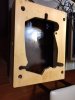
- It came on a really poorly made plywood plinth. I'm not going to throw it out though because the cut-out on the top was done pretty well. That could form the start of a better wood plinth in the future.
- I managed to win one of the original plastic plinths on the big auction site for exactly a Dual 604.
- Missing one of the spring suspension cups that sit on the bottom of the suspension spring.
- The counter-weight has the floppiness problem that most report for this model. I think I know what to do. Already have the weight disassembled.
- Missing the shipping screws. While I don't plan on turning it upside down, I don't relish having empty holes on the top of the plate.
- The cables that came with it are not the originals. Luckily the plastic plinth has a set. It will be a small challenge to figure out how to hook it all up.
- It came with the original Dual branded AT cartridge. I think it is a DMS242E. Going to need to find a new stylus for it.

EDIT: It turned out to be a Dual DMS 240 E cartridge.
 
Last edited:
Register to hide this ad
I see where I've created this in the wrong forum. Could an admin please move this to the Turntable forum please?
 
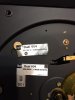
I've opened it up and started cleaning and examining it. The plastic plinth I bought came with new cables. The ones attached to the turntable were cut and patched so I was eager to replace them. In looking at the plinth it had a sticker that obviously fell off the original TT. It said 110-125V. My actual TT has a similar sticker that says 220-240V - indicating that maybe this came from outside the USA. That would explain why the cables were cut to replace the plugs on the end. I did plug in the TT and it has enough power to run at the correct speed, so maybe a previous owner made a change for US voltage. I'll have to check the voltage at the secondary of the transformer under the TT to verify. I checked the service manual and there isn't good info on how to make that change, so it is difficult to visually verify for me.

Here's a pic with both stickers. The one on the bottom is attached to the TT.


IMG_0688.JPG
 
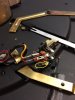
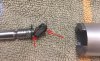
Found a thread about the drooping counter weight. It talks about gluing the felt pad to the L-bracket at the end of the counter weight arm. I used JB Weld epoxy at the two points shown. This helped, but there was still sag, so I bent the end of the L-bracket that has the screw hole on it to help tilt the weight upward a bit. It helped. After assembly the weight is not resting on the bottom of the counter weight shell anymore. I had to clamp the felt pad on the L-bracket to put a twist to the felt pad to get some upward tension on it. I used some needlenose pliers and taped them closed overnight. It turned out ok, but the weight isn't swinging freely as I expected. I tried adjusting the screw in the center of the counter weight and that appears to provide some adjustment but it also creates a mechanical stop that prevents the weight from swinging freely so it is a toss-up as to whether this whole design met its goal of some kind of vibration or oscillation canceling scheme.


IMG_0685.JPG IMG_0690.JPG
 
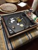
Here's some pics of the TT and the correct plastic plinth. Actually, I don't mind the faux woodgrain plastic plinth. Looks pretty good overall. I see a lot of people not liking it. I'm not feeling the same way.

Note the sticker from the TT that was originally in the plinth in the first pic.

IMG_0684.JPG
IMG_0689.JPG
 
Here's a pic of the original wiring on the TT before replacement. I noticed that the installation was a bit different in terms of placement of the plastic wire hold-downs. I think someone was also inside the TT and changed the wiring around somewhat. When replacing the wiring with what came with the plinth, I followed the service manual pics for routing the wires.

Another minor difference is that the audio cables that came with the TT had only one ground and the audio cables that came with the plinth had two - one for each channel. Not sure if that is a manufacturing difference or if someone was changing that cable as well. See circled in red where the wire lug (red) connected to the ground spade (red). See circled in yellow where the ground for the other channel was not used because the cables didn't come with a separate ground. (I don't think this is a problem as I'm assuming the single ground was servicing both channels, but just noticing a difference and wondering why.)

EDIT: Found the wiring diagrams for the audio cables in the service manual. This was apparently a non-USA model as the models with a "DIN" audio connection shows only a single ground wire which matches what I was seeing on the sticker (220-240V). This was likely a European model brought to the USA. That explains why both the AC and audio cables were cut. Someone was trying to convert this TT for USA and chopped the cables. Well, I have the correct (for USA) cables now installed. When I'm done with the refurb I'll report if it all works properly.

IMG_0687.JPG
 
Last edited:
Found the cup that supports the spring suspension on the big auction site.

- Missing one of the spring suspension cups that sit on the bottom of the suspension spring. (I've got a couple of 1009's and a 1226 in the queue. Wondering if I can borrow one temporarily or if they aren't compatible.)
- Missing the shipping screws. While I don't plan on turning it upside down, I don't relish having empty holes on the top of the plate. (Longer term.... When I can find them on the big auction site.)
- It came with the original Dual branded AT cartridge. It is a DMS242E. Going to need to find a new stylus for it. (I'd like to get a good quality stylus, if anyone has recommendations.)

Also...
- Need to clean and lube the TT. I'll use the service manual available on VE for that. (Already started and about 50% done.)
- Wondering if I should be replacing the capacitors throughout. There seems to be an anti-sparking cap at the AC terminals under the TT and there is a ckt board with multiple electrolytics on it. I imagine that is for the speed control

Any thoughts on should I replace those caps?

EDIT: It turned out to be a Dual DMS 240 E cartridge.
 
Last edited:
Borrowed a cup from one of my 1009's still in the queue. Fit perfectly. Got more on the way so I'll be able to replace it.

Question to experts. Is there any lubrication that can be done on the motor on the 604?
 
Got a problem.

I was lubing the anti-skate mechanism via the service manual and the knob spun on the AS. How do I re-calibrate it so that I know what are the settings?
 
If the anti-skate is like the rest of the turntables made by Dual, then simple. The hole in the white cam represents 'zero', so set dial to zero and rotate cam to suit and secure nut. And oiling the motor? Isn't it crimped shut?
 
If the anti-skate is like the rest of the turntables made by Dual, then simple. The hole in the white cam represents 'zero', so set dial to zero and rotate cam to suit and secure nut. And oiling the motor? Isn't it crimped shut?

NoTransistors,

Thanks. I'll rotate the cam for the AS and get it zeroed. That helps. Can I assume that the zero is the most relaxed setting for the spring?

In regards to the motor, I'll have to check, but it may very well be crimped shut. I'm assuming that your meaning is that it is not supposed to be serviceable. Am I correct in that assumption?
 
I have serviced plenty of Dual 701. Not supposed to be oiled, 'Serviced for life', they warn. But I do it anyway.

Yours is an entirely-different design. Need a can opener for it.

And yes, that locator hole represents the least amount of bias.
 
I have serviced plenty of Dual 701. Not supposed to be oiled, 'Serviced for life', they warn. But I do it anyway.

Yours is an entirely-different design. Need a can opener for it.

And yes, that locator hole represents the least amount of bias.

Thanks NoTransistors,

I'll check for noise and speed stability from the motor and if it isn't acting up I'll leave the motor alone. Not interested in doing surgery if the motor doesn't need it and the design makes it difficult.

Do you think I should be replacing the four electrolytics and the anti-sparking cap on this 604? What's your recommendation?
 
I had to look at my literature. In some ways, your table is laid out like a 701. The power box is separate. What happens with these things is the fuse will eventually blow because one of the caps in that metal box shorts. The caps here are NOT for the motor, but rather for the strobe, of all things.
 
I had to look at my literature. In some ways, your table is laid out like a 701. The power box is separate. What happens with these things is the fuse will eventually blow because one of the caps in that metal box shorts. The caps here are NOT for the motor, but rather for the strobe, of all things.

NoTransistors,

Ah, live and learn. I was assuming it was a controller for the motor speed. I'll get some replacements for those caps and replacement them. That will hold it for the next 20 years.

I'm close to having it ready to test soon (w.o. the new caps of course.) Next item is to source a good eliptical stylus for the DMS242E cart on it. I'm seeing cheap aftermarket ones on the big auction site, but not sure if there aren't better options available.

EDIT: It turned out to be a Dual DMS 240 E cartridge.
 
Last edited:
Your rectifier is in the transformer box, but the caps for the strobe and the fuse are still both on the line side of the transformer. The 701 has the rectifier on the main board. No biggie. Same outcome. Best of luck.
 
Your rectifier is in the transformer box, but the caps for the strobe and the fuse are still both on the line side of the transformer. The 701 has the rectifier on the main board. No biggie. Same outcome. Best of luck.

NoTransistors,

I missed your meaning on this post. Are you suggesting that I should replace the rectifier?
 
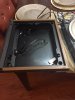
So just for fun. Here are pics of the home-made plinth that came with it. As it turns out it wasn't plywood, but still not a beautiful job. Trying to determine if I will save the top or if the whole thing ends up being firewood.

IMG_0693.JPG IMG_0692.JPG IMG_0691.JPG
 
Back
Top Bottom