• The move to the new server is done. There are some software and database maintenance updates in process. This has us passing the hat around to help out. We appreciate any donations. Seriously, even a dollar helps. The payment page may be found here - https://www.audiokarma.org/support.html

Repair help on my F-2624 on my Sansui 9090DB

degdug

New Member
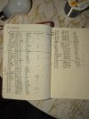
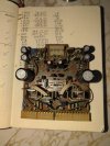
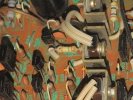
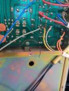
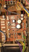
I'm currently having an issue on my 9090DB where the protection light does not come on and it does not click. From digging around forums, I believe that the F-2624 board is the problem. Attached are the resistor values that I obtained, photos of the board, and a fusible resistors that looks and reads as it failed. I already bought a complete capacitor kit for the 9090DB.

Have I found the source of my problem?

I see a kit on eBay for a full F-2624 rebuild for $40. Should I buy it or individually source only the resistors?
 

Attachments

  • 17528857810271724175170934467993.jpg
    17528857810271724175170934467993.jpg
    106.9 KB · Views: 31
  • 17528858671643114093225201737389.jpg
    17528858671643114093225201737389.jpg
    108.4 KB · Views: 31
  • 17528858953013616654106320579163.jpg
    17528858953013616654106320579163.jpg
    130.6 KB · Views: 31
Register to hide this ad
I'd say there's a great chance this is the source of the problem. There are a number of fusible resistors on the board....like the 150's you show wildly out of spec or open.......& ALL should be replaced. As far as ordering parts, if this isn't a hobby for you then perhaps just ordering the kit is the way to go. But do some homework on the seller......make sure they're selling quality parts.
 
I'd say there's a great chance this is the source of the problem. There are a number of fusible resistors on the board....like the 150's you show wildly out of spec or open.......& ALL should be replaced. As far as ordering parts, if this isn't a hobby for you then perhaps just ordering the kit is the way to go. But do some homework on the seller......make sure they're selling quality parts.

I appreciate your input! I went ahead and bought a rebuild kit from the seller in Milwaukee. I've heard good things on other forums.

My issue is I'm not getting any light on the protection indicator on the faceplate. Not even blinking red. I noticed about 50V of power was being sent to the protection board.

I'm a novice. My thought process is:

2624 has known faults. Potential failed resistors and other issues. This may be causing for excess voltage appearing in other parts of the system.

I've read online talking the 2624 board out should take it out of protection but that doesn't make much sense to me and nothing changes when I do that anyways.

Would you still believe the 2624 board to be the primary issue, or should I focus on the 2656, where the protection board is receiving power from?
 
Replace the fuse resistors. Even if they're not blown, they usually have drifted. Rebuild the driver board if you have already bought a kit. Sometimes a transistor will be problematic or have been damaged. I would have recommended "affinity for artifacts" (peace.love.andmusic) on ebay, but you've already purchased. AFA includes quite detailed and easy to follow instruction sheet for novices. AFA is a member on this board. I used his kit on my 8080DB and it's quite good.

Put the board back in and fire it up on a DBT. If it still doesn't come out of protection, do the ac bias adjustments and then the DC offsets. If it won't come out of protection, you'll have to do the dc offsets where it enters the relay board as opposed to at the speaker terminals as the service manual states.

If the relay board "sees" something wrong with the DC offsets, it won't come out of protection. That's why you'll need to check it where it enters the relay board.

You should check the ac bias and DC offset even if it does come out of protection since you've changed components on the driver board. If your kit included the pots and you change them, you'll be doing them anyways.

That fixes most of them that won't come out of protection. You'll have to go deeper into the power board and such if that doesn't do it. There's other trouble spots on these, but that will get you started.

Be careful installing the driver board. It can be installed one pin off easily and if that happens, you will short some things out, including blowing a circuit trace clean off the power board....don't ask me how I know......:rolleyes:
 
Last edited:
I have a 9090DB on the bench right now. The customer left it with solder monkey for recapping. Two years go by and it still doesn’t work so, it makes its way to my shop.

Long story short, only two of the dozen caps replaced were bad. Cap rework caused severe damage to PCB pads and traces with one severed bilateral trace that was left floating. After I restored heavy handed rework damage on the PCB and replaced a pair of underrated “Kit” capacitors, I have no audio on any source, probably the original complaint.

Old school troubleshooting

> all sources are heard on REC outputs and nothing on pre-outs
> protection cycles to green when speaker fuses are removed
>> Amp end of fuse reads -11VDC on both channels
>>> PNP output transistors are blown
> volume control is internally shorted

Parts on order
 
That raises a good point: make sure you’re using a good temp controlled iron and if possible, a good desolder gun.

The circuit traces on the X0X0 Sansui's are all old by now and they’re a bit delicate to start with. Its very easy to lift a solder pad.

I had to go through mine and “point to point” some places due to careless previous owners. Couple spots the traces had just gone “open”, I assume from age.

this is not the place for some high wattage solder “gun”.

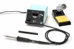
I use a weller wesd-51:

IMG_9001.jpeg

temp controlled tip. Quite precise on tip temperature.

Two schools of thought on soldering these: nice and low temp to protect the traces and higher temp quickly to “get in and get out” to minimize as much heat duration on the traces.

I tend to use the “get in get out” method, bit I’m also used to it.

For desolder I use an S-933a:

IMG_8999.jpeg

You can get by with solder wick or a manual solder-sucker, but this makes the job sooo much easier and far less chance of lifting a pad or trace. Hakko makes some good ones at good prices too.
 
Replace the fuse resistors. Even if they're not blown, they usually have drifted. Rebuild the driver board if you have already bought a kit. Sometimes a transistor will be problematic or have been damaged. I would have recommended "affinity for artifacts" (peace.love.andmusic) on ebay, but you've already purchased. AFA includes quite detailed and easy to follow instruction sheet for novices. AFA is a member on this board. I used his kit on my 8080DB and it's quite good.

Put the board back in and fire it up on a DBT. If it still doesn't come out of protection, do the ac bias adjustments and then the DC offsets. If it won't come out of protection, you'll have to do the dc offsets where it enters the relay board as opposed to at the speaker terminals as the service manual states.

If the relay board "sees" something wrong with the DC offsets, it won't come out of protection. That's why you'll need to check it where it enters the relay board.

You should check the ac bias and DC offset even if it does come out of protection since you've changed components on the driver board. IF you kit included the pots and you change them, you'll be doing them anyways.

That fixes most of them that won't come out of protection. You'll have to go deeper into the power board and such if that doesn't do it. There's other trouble spots on these, but that will get you started.

Be careful installing the driver board. It can be installed one pin off easily and if that happens, you will short some things out, including blowing a circuit trace clean off the power board....don't ask me how I know......:rolleyes:
Incredible. Thank you for such a thorough response! I'm pretty sure this unit has been serviced before. I noticed this on the back. Is this what blowing the circuit trace looked like to you? How did you fix/recommend fixing for this power board?
 

Attachments

  • 17534815998067521240867191568244.jpg
    17534815998067521240867191568244.jpg
    109.2 KB · Views: 25
yep, that trace is gone. Vaporized.

That's the trace that goes "poof" when someone has put the driver board in 1 pin off. You can repair it with a small insulated wire from where it starts to where is ends. That's what's commonly referred to as a "point to point" repair.

The unit will not work with that trace blown.

That can also damage components on the driver board. You may see one blackened slot in the white multi-connector on the driver board. This is caused by the arc when it's one pin off.

In consideration of all this and that you already have a "kit", I'd just go right to rebuilding the driver board.

There's also a transistor on the power board that may be damaged, but fix the other stuff first and see what you get.

definitely build yourself a DBT if you don't already have one.

Also, when you rebuild the driver board, only do one component at a time. Some of the transistors can be marked incorrectly on the silk screening so you want to put the new ones back in the way the old ones came out. Take a good, clear hi res photo of the whole driver board from straight above before you start. A few from all four sides is also a good idea. If you're an amateur, pictures are you friend. The more, the better....
 
Last edited:
yep, that trace is gone. Vaporized.

That's the trace that goes "poof" when someone has put the driver board in 1 pin off. You can repair it with a small insulated wire from where it starts to where is ends. That's what's commonly referred to as a "point to point" repair.

The unit will not work with that trace blown.

That can also damage components on the driver board. You may see one blackened slot in the white multi-connector on the driver board. This is caused by the arc when it's one pin off.

In consideration of all this and that you already have a "kit", I'd just go right to rebuilding the driver board.

There's also a transistor on the power board that may be damaged, but fix the other stuff first and see what you get.

definitely build yourself a DBT if you don't already have one.

Also, when you rebuild the driver board, only do one component at a time. Some of the transistors can be marked incorrectly on the silk screening so you want to put the new ones back in the way the old ones came out. Take a good, clear hi res photo of the whole driver board from straight above before you start. A few from all four sides is also a good idea. If you're an amateur, pictures are you friend. The more, the better....
Hell yeah! Excellent lead! I'm going to focus on the driver board now.

I am a novice. I'm positive somebody has worked on this unit before me judging from unique resistors on the driver. I have it plugged into a DBT. Fortunately it doesn't seem like there is a short circuit!

I've already noticed some transistors non-functional on the power supply. Wow. It feels incredible seeing something that I really feel could be the problem! I'll dig deeper as soon as I can. I greatly appreciate this input!
 
That trace burns when you install the driver board one pin off. (Don't ask how I know)

- Pete
 
Alright guys! I got it out of protection mode!

The problem was the bridge rectifier. I replaced the diodes and bridges the outer leads from behind with jumper cable. I also replaced TR01, R30,31,32 and the zener diode. On to the driver board and potentially Dolby board!
 

Attachments

  • IMG-20250804-WA0017.jpeg
    IMG-20250804-WA0017.jpeg
    110.3 KB · Views: 23
Okay, It was working until I decided to replace the 2 outer trimmers and a diode. I wasn't finding the reading I was looking for so I started turning them left and right. Nothing. Did I blow a transistor trying to get this trimmed out???
 
Back
Top Bottom