• The move to the new server is done. There are some software and database maintenance updates in process. This has us passing the hat around to help out. We appreciate any donations. Seriously, even a dollar helps. The payment page may be found here - https://www.audiokarma.org/support.html

Resistor questions

DennisK2021

AK Subscriber
Subscriber
I have read a 2009 post on this but still have a few questions. I had been mostly ignoring resistor type, etc and just focusing on value. Seems to have worked fine when I replaced all the resistors in my Pilot 500 but now I wonder. I have been reading some content on resistors and noise, also something on using good quality plate resistors. I got a bunch of resistors, offered as a vintage kit, when I needed to get to a min order from Just Radios. The 20 pack resistors do not have much info and seem small and cheap. I'll try to avoid using those. Selected resistors from them seem better.

What I think:

1. Plate resistors should be min 1W Metal Oxide, the larger size and MO construction are better for noise.
2. A number in parenthesis following a resistor designation is wattage.
3. The old, longer, smooth resistors are wire wound, maybe non-inductive wire wound (ie, a green Mallory 12,000-1 3/4" long x 3/8" diameter)

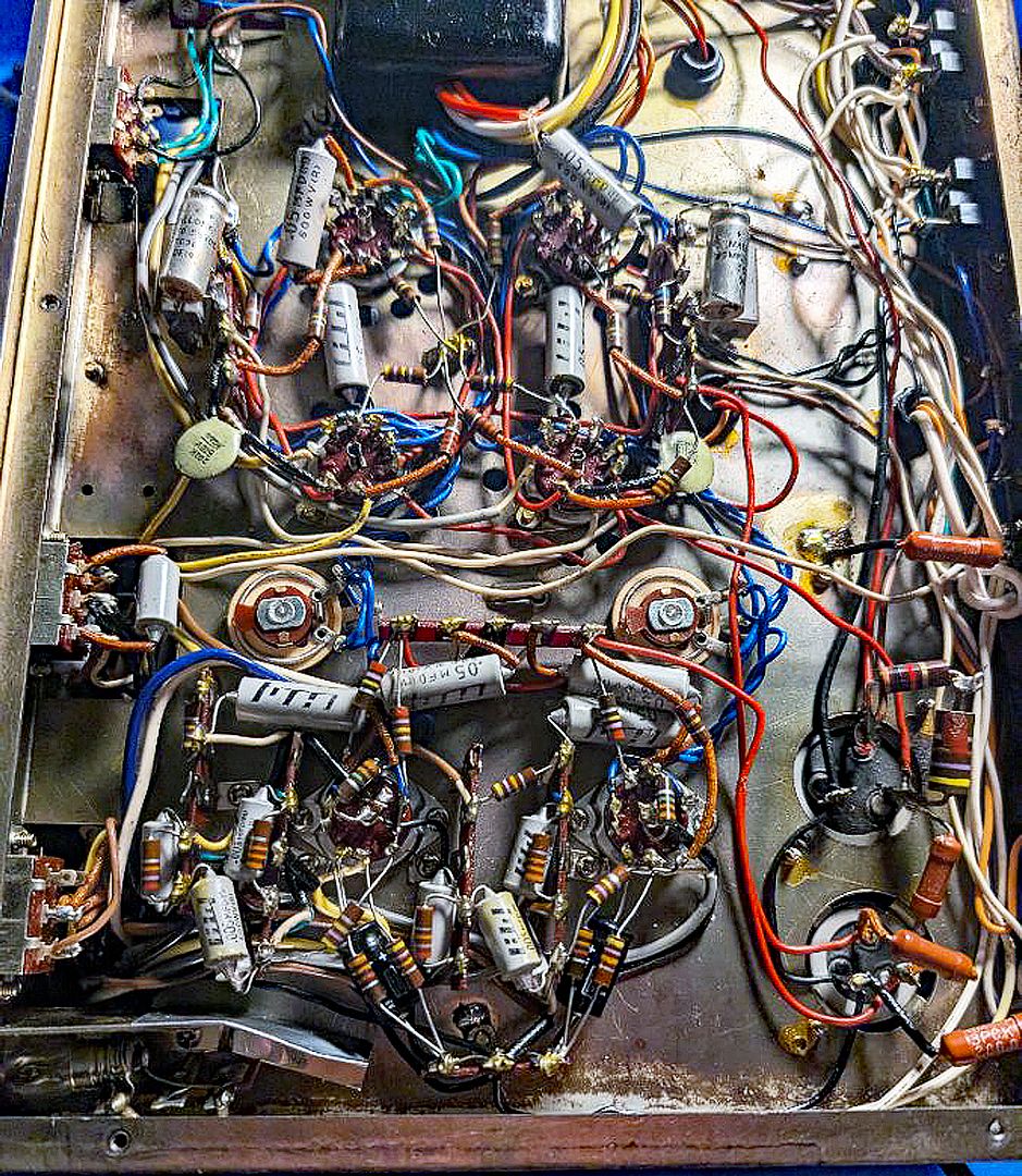
I picked up a Japanese Monarch as I liked the quirky beam triodes and I needed more practice. The circuit is below. The resistors between the power filter can caps were brown units that look like the small versions of the Mallory. It looks like both of the can multi electrolytics were replaced. The 1st 20/20 can has been replaced by a 20/40 and the resistor between the 40&20 has been replaced by a largish film 470 Ohm in series with a smaller 100 Ohm. I think the capacitance was increased to eliminate noise, which was unsuccessful. The resistor value may be somebody confused by color bands? The other resistors are the brown guys and are the 5K and 30K. There is another brown, smooth resistor (200 Ohm) between the ground of the 20/20 can and chassis ground that I don't see on the circuit but it looks original.

The 25uF electrolytics between the power tube cathodes are silver Mallory. The associated 3W resistors are 750 Ohm WW cement in lieu of the 200 Ohm 3W. I can't find the other two 200 Ohm 3W resistors for the output transformers. The headphone jack resistors are black and the wire wraps are visible below the black skin. I plan to leave all the wire wounds in place unless there is an issue during initial testing. I do plan to address the 20/40 can. I can sub individual 20uF electrolytics before I buy another 20/20 can.

Any comments, suggestions are welcome including criticisms, I have thick skin.

SA_40A schm.jpgBottom Pic.jpg

Looking on-line, I can find the missing WW for the electrolytic can, 2W metal film resistors for all the tube plates and 1 or 2 W metal for cathodes. I'm thinking carbon composite for grid resistors (having trouble finding those) and what I have on hand for the rest. Does that make any sense?

PS: the 200 WW at the 2nd can ground, along with the same from what looks like an OPT ground spot, may be the 2 200Ohm WW I was looking for. I still wonder at the 750Ohm Masonite WWs in lieu of the other 200Ohm 3W resistors.

Moved from DIY
 
Last edited:
Register to hide this ad
You’ll need to post the URL addresses. Or upload the photos to your computer, then repost them here.

I'm getting this error message: "You do not have permission to view this page or perform this action"
 
48d72bdf-c7f2-4bb4-982b-fa73c6149a55.jpg


I have one other suggestion. All of the Japanese paper-in-oil coupling caps (gray) are prolly going to need to be replaced.

They are notorious for failure (leaking DC voltage). To keep the tubes happy, replace them with quality non-polar poly caps. Same voltage, same mfd.

Another source.
 
Last edited:
If you are concerned about resistor self noise you may want to read the technical paper from Vishay on the subject.
Most resistor types will have their own sonic signature.
Metal oxide are very robust and will take a lot of abuse but sonically can add a metallic sound to the signal.
carbon comps have a nice sonic signature but tend to drift and be a bit noisy.
Metal films vary widely depending on who the manufacturer is.
If you are looking at wire wound, you may want to consider the MILLS wire wound which can take the heat and the voltage and still sound very quiet.
 
48d72bdf-c7f2-4bb4-982b-fa73c6149a55.jpg


I have one other suggestion. All of the Japanese paper-in-oil coupling caps (gray) are prolly going to need to be replaced.

They are notorious for failure (leaking DC voltage). To keep the tubes happy, replace them with quality non-polar poly caps. Same voltage, same mfd.

Another source.
I have all JB-JFK caps to replace the Jap gray things. They are Taiwanese, fairly inexpensive and supposed to be fairly good. Haven't used them, but it was easy to get all the values I needed.

If you are concerned about resistor self noise you may want to read the technical paper from Vishay on the subject.
Most resistor types will have their own sonic signature.
Metal oxide are very robust and will take a lot of abuse but sonically can add a metallic sound to the signal.
carbon comps have a nice sonic signature but tend to drift and be a bit noisy.
Metal films vary widely depending on who the manufacturer is.
If you are looking at wire wound, you may want to consider the MILLS wire wound which can take the heat and the voltage and still sound very quiet.
I will look for the Vishay paper, I know that's a good brand but sourcing those isn't easy. The metal film 2W for the tube plates to reduce noise and handle the power seem like a good idea. Min 1W, 1% for the cathodes for accuracy and stability of components affecting tube bias. I don't think either of those are in the signal path.

I'm guessing the old resistors are carbon. The 2 I've removed and checked were 6% and 7% high. I'm considering keeping most. Any that are out more than I like I can probably replace with eBay old stock. One seller has Allen-Bradly carbon composites. Any comments on 60s carbon resistors?

The Metal resistors I've found are TDK and offer matched pairs. The WW, to replace the missing one in the power section is MILLS.
 
Duh, the plate resistors are part of the amplified signal path, aren't they? I still think MO are the way to go there.
 
1. Plate resistors should be min 1W Metal Oxide, the larger size and MO construction are better for noise.
Hi Dennis,

Might be good to become familiar with Ohm's law so you can check power dissipation issues with resistors and not just guess at what a good wattage rating might be. 1W isn't always a high enough rating for reliability and metal film is probably what you want for a plate resistor. Metal oxide are good in power supplies as they are fairly robust. Not so good in the audio portion of the circuit. If you know the voltage across a resistor and its value you can easily calculate the power dissipated in that resistor and then get a watt rating that is conservatively higher for reliability.

Have fun
 
Old carbon resistors are prone to noise and value drift. Noise really only in current paths though, so plate or cathode mostly. Grid resistors aren't dealing with current but significant drift can alter turnover frequency when a cap feeds into it. Mostly a problem in tone controls and phono EQ circuits.

My 2 cents, but there is almost no circumstance where I would actually seek out 60 year old resistors to put in anything but a trash can. If you're allergic to metal film, carbon film are vastly more stable and quiet than CC types and aren't period incorrect. Old vapor deposit resistors are just an older form of carbon film, used in circuits where stability and low noise were key.
 
I suspect there are various different types of metal oxide resistors. I'm always suspicious of them because I used to build high voltage amplifiers and found metal oxide resistors in the feedback path had a voltage coefficient and caused significant distortion. OTOH, maybe new ones are better. Their claim to fame is robustness.

AFAIK, wire wound resistors have the lowest thermal noise but there is no such thing as a truly non-inductive wire wound. Low, yes, but I've seen non-inductive wire wound load resistors increase the THD at high frequencies, 10 kHz and up. The construction was two layers, wound in opposite directions. Precision resistors are wound on multi section bobbins, changing direction for each section. You're unlikely to find those in audio equipment, nor would I seek them out for anything other than precision DC applications.

Carbon film is really quite good but I don't bother with them because metal film is so inexpensive.

I use metal film resistors for just about everything. The inexpensive ones from Digikey seem fine and I buy them 200 per bag. For tube amps you have to pay attention to the voltage rating and often need to seek out RN70D parts. All resistors have a voltage and power rating and you should know what it is.

Probably not relevant here but I've found excessive noise levels from thick film resistors and avoid them. I think excess noise is current dependent. Geller Labs is long gone, but you can learn a lot about noise from this article- https://physicsopenlab.org/wp-content/uploads/2016/10/JCan-NV-article.pdf
 
I suspect there are various different types of metal oxide resistors. I'm always suspicious of them because I used to build high voltage amplifiers and found metal oxide resistors in the feedback path had a voltage coefficient and caused significant distortion. OTOH, maybe new ones are better. Their claim to fame is robustness.
Believe me, the old PIO Japanese caps are prolly 10X noisier than the old carbon comp resistors. And 10X more potential problems for the tubes (leaking DC voltage).

That's the first priority of this amp. Not the resistor type used to replace the old CCs (that's a distant number 3 on the list — after replacing the main power supply and, if it has one, the bias supply filter caps and resistors).

:thumbsup:
 
OP said they were replaced, so hopefully thats no longer a factor.

If distortion problems remain and it doesn't move with tubes, there is some faulty component in the channel. Could be a lot of things, need to do some isolation to narrow it down but checking voltages against the channel that works will often provide a clue.
 
OP said they were replaced, so hopefully thats no longer a factor.
Were the coupling caps replaced? Or just the main filter caps?

He also needs to replace the CC resistors in the power supply and bias supply with quality metal-oxide (or film or wire-wound) resistors.
 
Last edited:
I have all JB-JFK caps to replace the Jap gray things. They are Taiwanese, fairly inexpensive and supposed to be fairly good. Haven't used them, but it was easy to get all the values I needed.
Were the coupling caps replaced? Or the main filter caps?


I interpret that as coupling caps, though on a re-read it may be that parts are on hand but not installed. Either way it sounds like its being handled. The electrolytic probably need to be done as well if they haven't been already.

but yea I'd definitely deal with cap problems first, then proceed from there as needed. I know its kind of a lazy answer to say "change the caps" but there is solid reasoning for it.
 
but yea I'd definitely deal with cap problems first, then proceed from there as needed. I know its kind of a lazy answer to say "change the caps" but there is solid reasoning for it.
Yeah, those old PIOs could be pouring DC onto the grids of the tubes they are coupled to. That is definitely causing noise and shortening tube life.

"They's gotto go!"
 
Back
Top Bottom