

You are using an out of date browser. It may not display this or other websites correctly.
You should upgrade or use an alternative browser.
You should upgrade or use an alternative browser.
Resistor questions
- Thread starter DennisK2021
- Start date

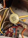
Thanks to everyone. I have more questions. One is the 750 Ohm cement WW resistors that look original. They obviously had the 200 Ohm orangey brown ones. Any idea why the change? Another question is this ceramic that I'm not finding on the circuit diagram. There are 2 each attached to pin 9 of two of the 6MB8s. On Frank's data sheet, that's the grid of the pentode half of the 2 of the 6MB8s. On the circuit diagram, pin 9 is the plate of the triode half. I should be able to trace out what that pin actually is but that doesn't address why the ceramics are there. And what are they?
Also, while I'm here, the 25uF electrolytics are nice looking silver Mallory units. The ones I bought to replace them don't look spectacular. If the Mallory caps measure correctly, can I keep those?
Also, while I'm here, the 25uF electrolytics are nice looking silver Mallory units. The ones I bought to replace them don't look spectacular. If the Mallory caps measure correctly, can I keep those?
Last edited:

If you want expensive, I just assembled a board yesterday, to go into a phono preamp, that uses FOURTEEN Vishay Z-Foil "naked foil" gold foil resistors on it. Including a couple of 200K resistors, which are the most expensive ones in that series (the higher the resistance, the higher the price, due to the manufacturing/etching required).
That was just for the phono loading daughterboard.
In this phono preamp, the main RIAA/gain board uses another dozen or more Vishay "naked foil" resistors, as well as a dozen or more Caddock MK series and four Caddock MP series resistors on it.
I think that's the most expensive collection of resistors I've ever assembled, so far.
Regards,
Gordon.
Thanks but not looking to spend a lot on the Jap Monarch, just couldn't pass on the triode/pentode tube unit. The supplier for the TDK resistors does have Allen Bradley carbon composite resistors but, given the number of resistors in this thing, I'll wait to see what I actually need.If you want expensive, I just assembled a board yesterday, to go into a phono preamp, that uses FOURTEEN Vishay Z-Foil "naked foil" gold foil resistors on it. Including a couple of 200K resistors, which are the most expensive ones in that series (the higher the resistance, the higher the price, due to the manufacturing/etching required).
That was just for the phono loading daughterboard.
In this phono preamp, the main RIAA/gain board uses another dozen or more Vishay "naked foil" resistors, as well as a dozen or more Caddock MK series and four Caddock MP series resistors on it.
I think that's the most expensive collection of resistors I've ever assembled, so far.
Regards,
Gordon.
You guys have tons of experience. I'm kind of just getting going. I'll probably go through the Pilot amp again after this and I have a Magnavox 8802 that's been in the closet a while. The Citation 5, though, is going to someone who actually knows what he's doing.

Thanks to everyone. I have more questions. One is the 750 Ohm cement WW resistors that look original. They obviously had the 200 Ohm orangey brown ones. Any idea why the change?
Also, while I'm here, the 25uF electrolytics are nice looking silver Mallory units. The ones I bought to replace them don't look spectacular. If the Mallory caps measure correctly, can I keep those?
View attachment 3858347
1.) This is a 200 picofarad disc capacitor. They last forever. Leave it be.
2.) I would replace the 25mfd silver Mallory electrolytic cap. That one looks like 1960-70s vintage (prolly OEM). A Sprague ATOM of equal value will be fine.
3.) Wire-wound "brick" resistors usually last forever, unless physically damaged. Leave them be.
Last edited:
Replace the electrolytic and gray coupling caps first. Use a dim light bulb tester while ramping up with the Variac. Measure the voltages and compare them to the schematic. Try using a good digital volt-ohm meter. Set to hundreds of volts DC.Thanks but not looking to spend a lot on the Jap Monarch, just couldn't pass on the triode/pentode tube unit. The supplier for the TDK resistors does have Allen Bradley carbon composite resistors but, given the number of resistors in this thing, I'll wait to see what I actually need.
You guys have tons of experience. I'm kind of just getting going. I'll probably go through the Pilot amp again after this and I have a Magnavox 8802 that's been in the closet a while. The Citation 5, though, is going to someone who actually knows what he's doing.
Listen to the unit. If it sounds fine, don't worry about the resistors. If it still has noise, you can do a wooden-chopsticks tap test to see if you can locate damaged or poorly soldered resistors, and replace ONLY those first. Try to resist a wholesale change to all the resistors. Take plenty of before photos to help prevent miswirings and wrong soldering.
Keep your free hand off the chassis when the unit is "hot" during the wooden chopsticks test.
Good luck! Take your time. And plenty of good close-up photos. Before and after each stage of the restoration.
Last note: Watch the polarity of ALL electrolytic caps!

Last edited:

1.) This is a 200 picofarad disc capacitor. They last forever. Leave it be.
2.) I would replace the 25mfd silver Mallory electrolytic cap. That one looks like 1960-70s vintage (prolly OEM). A Sprague ATOM of equal value will be fine.
3.) Wire-wound "brick" resistors usually last forever, unless physically damaged. Leave them be.
Thanks, I'll grab a couple of Sprague E caps.Replace the electrolytic and gray coupling caps first. Use a dim light bulb tester while ramping up with the Variac. Measure the voltages and compare them to the schematic. Try using a good digital volt-ohm meter. Set to hundreds of volts DC.
Listen to the unit. If it sounds fine, don't worry about the resistors. If it still has noise, you can do a wooden-chopsticks tap test to see if you can locate damaged or poorly soldered resistors, and replace ONLY those first. Try to resist a wholesale change to all the resistors. Take plenty of before photos to help prevent miswirings and wrong soldering.
Keep your free hand off the chassis when the unit is "hot" during the wooden chopsticks test.
Good luck! Take your time. And plenty of good close-up photos. Before and after each stage of the restoration.
Last note: Watch the polarity of ALL electrolytic caps!
When you say to avoid wholesale resistor change, do you think I should not swap out the pate and cathode resistors? It is only $35 for all those. The expensive one is the missing power resistor.
Look, you can do whatever you want. AFTER you change the electrolytic and coupling caps. But I have a general suggestion...When you say to avoid wholesale resistor change, do you think I should not swap out the pate and cathode resistors? It is only $35 for all those. The expensive one is the missing power resistor.
Don't do the resistor (even partial replacement), caps, and everything else all at the same time. If something doesn't work, you'll have PITA time figuring out where the problem is. Try to resist "wholesale change sentiment" and instead take a slow, systematic, step-by-step approach. Test each step afterward to be sure it's okay, before moving on to the next.
Take photos. Keep notes. Your mental health will thank you later.

Last edited:
I do find those ceramics on the schematic, off pin 9 of 2 triode sections of the 6MB8s, but they are 100pF on the plans. I'm going to assume there were factory changes back when.
1.) This is a 200 picofarad disc capacitor. They last forever. Leave it be.
2.) I would replace the 25mfd silver Mallory electrolytic cap. That one looks like 1960-70s vintage (prolly OEM). A Sprague ATOM of equal value will be fine.
3.) Wire-wound "brick" resistors usually last forever, unless physically damaged. Leave them be.
I've been reading. I think I haven't been soldering correctly. Sort of miraculous that the Pilot sounds as good as it does. Per what I'm reading and per anatech, one should clean all old solder off the tabs as it will interfere with the new solder. So any resistor on the same tab as a capacitor, needs to come off. Things were easier when I was comfortable cutting an existing lead and hacking in a new component.
Those ceramic discs look OEM. Don't touch them unless they are physically damaged.I do find those ceramics on the schematic, off pin 9 of 2 triode sections of the 6MB8s, but they are 100pF on the plans. I'm going to assume there were factory changes back when.
I've been reading. I think I haven't been soldering correctly. Sort of miraculous that the Pilot sounds as good as it does. Per what I'm reading and per anatech, one should clean all old solder off the tabs as it will interfere with the new solder. So any resistor on the same tab as a capacitor, needs to come off. Things were easier when I was comfortable cutting an existing lead and hacking in a new component.
I use my old Hakko 808 desoldering gun to desolder old solder. You can use a hand sucker — those take a bit more practice. Then, I lay down the new solder. A shiny, tiny dot is what you want for a good solder joint. I use a bit of Cardas rosin flux paste before each new solder, and a Weller soldering station with a medium-sized chisel tip.

I really like the sound of the Vishay "Pro2" series 2W metal films. The brick red color ones. I've settled on just stocking the 2W, they are reasonably small and the leads are thick enough to work well with point to point wiring. I've read over sized rated resistors are less likely to introduce noise too. For higher power resistors like the cathode on power tubes, I use wire wound and try to source non-inductive if I can find them.
On my 2A3 I did sub in a carbon film for the output tube grid leak and was surprised that it did take a little of the "edge" off. I originally built it with all carbon films and found it a bit soggy sounding for my taste. YMMV
On my 2A3 I did sub in a carbon film for the output tube grid leak and was surprised that it did take a little of the "edge" off. I originally built it with all carbon films and found it a bit soggy sounding for my taste. YMMV
I have all JB-JFK caps to replace the Jap gray things. They are Taiwanese, fairly inexpensive and supposed to be fairly good. Haven't used them, but it was easy to get all the values I needed.
I will look for the Vishay paper, I know that's a good brand but sourcing those isn't easy. The metal film 2W for the tube plates to reduce noise and handle the power seem like a good idea. Min 1W, 1% for the cathodes for accuracy and stability of components affecting tube bias. I don't think either of those are in the signal path.
I'm guessing the old resistors are carbon. The 2 I've removed and checked were 6% and 7% high. I'm considering keeping most. Any that are out more than I like I can probably replace with eBay old stock. One seller has Allen-Bradly carbon composites. Any comments on 60s carbon resistors?
The Metal resistors I've found are TDK and offer matched pairs. The WW, to replace the missing one in the power section is MILLS.
The two attached PDFs may help.