Hi! I have some amplifier recaps planned, and while checking over values of caps, i noticed something. One of the amps i plan to recap have some cracked resistors (just 2-3 of them), and another amp has some burned ones (or at least they look burned). So I thought I would just look up the correct values at mouser and be good to go, but there are a lot to choose from. So I open up the manual, and some of them say "O.M. Film" or "Carbon". Since I haven't changed any of those before, does it mean that I have to find the same type or can I go with something else too, as long as values match? Since I can't seem to find any O.M.Film resistors on mouser. (unless they are called something different now). I see some people recommend going metal film or carbon film for almost everything, when you are about to swap resistors. Would this work? Any help would be appreciated! Thanks.


You are using an out of date browser. It may not display this or other websites correctly.
You should upgrade or use an alternative browser.
You should upgrade or use an alternative browser.
Resistor swap help
- Thread starter GytisB
- Start date
Register to hide this ad

OM could be metal oxide or metal film. You could go with either one."O.M. Film" or "Carbon".
Carbon is carbon film..
Ohhhh, so any of those work! Thats great!OM could be metal oxide or metal film. You could go with either one.
Carbon is carbon film..
Thank you!Welcome to AK .. BTW

You should use Metal Oxide resistors for those that get hot in operation, as they can deal with the heat better than Metal Film types for example. Metal Film are much lower noise than Carbon Composition or Carbon Film and can be used to replace either, providing you use the correct wattage rating.
Note that changing the resistor type can slightly alter the sound characteristic of a unit, replacing a Carbon Composition with a Metal Film is likely to show the biggest change, although the effect is quite subtle.
Note that changing the resistor type can slightly alter the sound characteristic of a unit, replacing a Carbon Composition with a Metal Film is likely to show the biggest change, although the effect is quite subtle.
You should use Metal Oxide resistors for those that get hot in operation, as they can deal with the heat better than Metal Film types for example. Metal Film are much lower noise than Carbon Composition or Carbon Film and can be used to replace either, providing you use the correct wattage rating.
Note that changing the resistor type can slightly alter the sound characteristic of a unit, replacing a Carbon Composition with a Metal Film is likely to show the biggest change, although the effect is quite subtle.
Thats was a really good explanation, thank you!
Will take that in consideration!

If you can take pics and post them it would be easy to tell which type they are. Different types, and different power ratings, are used for different roles in an amp. Another thing to be aware of when you order resistors is their length, usually noted in mm. Matching length with the originals makes installation of the replacement easier and is, IMO, more aesthetically correct.

Retrovert
Addicted Member
The abbreviation "OM" or "O.M." in this context most likely refers to "Original Manufacture", to distinguish from a service memo or replacement part. It would not be "oxidized metal" or "oxide metal" as those names were not used for resistors.
Metal oxide resistors are nowadays uncommon. The advantage are higher power ratings, higher voltage ratings, a greater tolerance for higher external temperatures, greater tolerance for higher temperatures from pulse/overload conditions (typically about 30% higher than metal film), but the cost is significantly higher noise, abysmal Tcr (temperature coefficient of resistance), etc. Not a good choice for audio, unless one wants grit in a guitar amplifier or effect where noise and non-linear effects are valuable.
Metal film is now the preferred technology for audio. It is unusual that audio circuits would use high currents or require high temperatures requiring metal oxide.
Carbon film suffers from the same drawbacks as carbon composition, including Vcr, Tcr, noise, etc. Such components are used to meet a price point. Metal film costs a trivial amount more, and has far lower noise.
Metal oxide resistors are nowadays uncommon. The advantage are higher power ratings, higher voltage ratings, a greater tolerance for higher external temperatures, greater tolerance for higher temperatures from pulse/overload conditions (typically about 30% higher than metal film), but the cost is significantly higher noise, abysmal Tcr (temperature coefficient of resistance), etc. Not a good choice for audio, unless one wants grit in a guitar amplifier or effect where noise and non-linear effects are valuable.
Metal film is now the preferred technology for audio. It is unusual that audio circuits would use high currents or require high temperatures requiring metal oxide.
Carbon film suffers from the same drawbacks as carbon composition, including Vcr, Tcr, noise, etc. Such components are used to meet a price point. Metal film costs a trivial amount more, and has far lower noise.
Retrovert
Addicted Member
Note that changing the resistor type can slightly alter the sound characteristic of a unit, replacing a Carbon Composition with a Metal Film is likely to show the biggest change, although the effect is quite subtle.
One other comment.
I suspect Hyperion is referring to plate swings in tube amplifiers, not solid state which operate at much lower voltage. But, in any event, if the resistor changes the sound it is adding distortion. That may be distortion humans like, or distortions humans dislike, but it is, nontheless, distortion, so the amplifier is no longer a straight wire with gain.
Here's what I previously wrote on that subject, somewhat edited for content and brevity.
A carbon-composition resistor (CCR) is made from a mixture of clay (non-conductive) and carbon black (conductive). The ratio determines the resistance; more carbon = less resistance, while less carbon = more resistance. This grainy mix tends to act like a jumble of diodes which causes peculiar properties. (The diodes are not aligned, so the resistor does not have directionality.) This is similar to the varistors made from copper oxides. (That work on copper oxides, BTW, leads to Bardeen and Brattain collaborating as a team, and that, in turn, led to their stealing credit for the transistor from Russell Ohl. Neglecting that it had actually been invented by others decades before, and technically wasn't patentable because of all the prior art. Yes, this will be on the quiz.)
Anyway, the variable voltage drop of the diode effect give rises to a Vcr (Voltage Co-efficient of Resistance). The value of a CCR thus non-linearlly fluctuates with applied voltage: (If the resistance changes as the voltage fluctuates between high and low values, then resistor offers non-linear behavior, i.e. the change is lesser at the lower voltages and greater at the higher voltages.) If the voltage is relatively constant, however, which is the case for most resistors in an amplifier (dividers, bias, and the like), the resistor is just constantly out of specification, with the difference being a function of voltage and usually trivial for low (< 100 V) voltages. So it must be a plate resistor experiencing a large voltage swing, as nothing else in the amplifier has that kind of fluctuation.
The Erie Resistor Company found differences of a few percent over swings of several hundred volts. Others found 0.025% / volt for values below 1 MΩ and twice that, 0.05% / volt, for values above 1 MΩ. What that means, in practice, is at, say, 300 V the values below 1 MΩ would have about 7.5% drift and those above 1 MΩ would have about 15% drift. This is why it matters at the plate. This effect won't show up at low or constant voltages.
So all those CCR solid-state guitar amplifiers running with 35 V (or lower) rails? Nope. No benefit from distortion. And voltage dividers? They're just out of spec because the voltage across them is constant. (Neglecting trivial fluctuations in the supply, of course, for those who want to quibble.)
Solid-state uses low voltages compared to tubes, so Vcr tends to be irrelevant over the narrow swings with transistors. Yet I've seen guitar effects running on a 9 VDC battery claiming "carbon resistors for sound!" when that's simply impossible.
If you can take pics and post them it would be easy to tell which type they are. Different types, and different power ratings, are used for different roles in an amp. Another thing to be aware of when you order resistors is their length, usually noted in mm. Matching length with the originals makes installation of the replacement easier and is, IMO, more aesthetically correct.
Sure! Didn't think about that. Here it goes:
Technics SU8600.
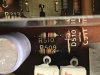
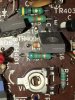
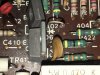
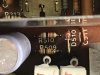
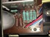
R509 and R510. One of them looks cracked, so I think of replacing both. What it says in the manual is also added.
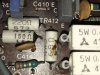
White ones, marked as 68ohm, 150ohm, 220ohm and 0.47ohm. 0.47ohms look like wirewound? but manual says something else. R437-442 and R445-448. Manual for these are added also.
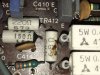
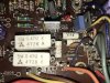
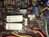
Green. R453-R456 and R507.
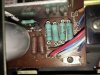
A few of those greens look strange too, so I might want to swap them too. R432, 420, 431, 419.
.
Manuals
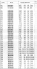

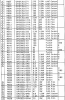
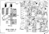
JVC R-X303V. Can't take pictures at the moment, but the schematics are here. I plan to swap R831-838 (these look alot like the green R453-R456 on the technics). Also R810-813, and R816-817.
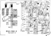
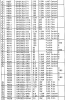
I think I figured out about Sony F808ES. Found this thread on AK https://audiokarma.org/forums/index.php?threads/sony-ta-f707es-f808es-burnt-fuse-resistors.814517/ . Mine is not burned yet, but gets really really hot in a 30-60 minutes. So I think it might be the problem here too? Wouldn't cost much to swap them, so I guess I will do it. Then ones I want to swap are fusibles. So I just stick to the same specs and go for metal film or metal oxide?
Attachments
-
 IMG_0428.JPG94.8 KB · Views: 71
 -
 IMG_0430.JPG130 KB · Views: 56
 -
 IMG_0431.JPG145 KB · Views: 39
 -
 IMG_0432.JPG115.2 KB · Views: 50
 -
 IMG_0435.JPG164.6 KB · Views: 44
 -
 IMG_0436.JPG120.2 KB · Views: 35
 -
 r440.PNG563.5 KB · Views: 19
 -
 r509.PNG72.2 KB · Views: 17
 -
 jvc.PNG562.4 KB · Views: 14
 -
 jvc2.PNG816.2 KB · Views: 16
I'm a firm believer in if it ain't broke, don't fix it. Those white resistors all look fine, some sort of ceramic. The one looks like it got some adhesive on it, and that turned brown when it got warm. Shouldn't hurt anything. The one cracked resistor should be replaced. I saw a diode under one of the green resistors that looks like it has a scorch mark on the board under it. Might need to replace that, and investigate why it got hot. Nothing wrong with the green resistors either.
I'm a firm believer in if it ain't broke, don't fix it. Those white resistors all look fine, some sort of ceramic. The one looks like it got some adhesive on it, and that turned brown when it got warm. Shouldn't hurt anything. The one cracked resistor should be replaced. I saw a diode under one of the green resistors that looks like it has a scorch mark on the board under it. Might need to replace that, and investigate why it got hot. Nothing wrong with the green resistors either.
Thanks for the input! Makes sense what you said here. I thought these were also broken. But if you mean that only a few of them, than I will just go for swapping those.
Retrovert
Addicted Member
The values for all of the resistors in question may be verified using a meter. Over-current conditions causes resistors to overheat and the excess power dissipation, may alter the value but this is not guaranteed. Because resistors are not fuses, such over-current conditions may be long tolerated without failure for hours, even days, with the jacket cooked to the point of a severe alteration in color.
The cement-coated wirewound resistors will tolerate considerable heating without damage. As a guess I would surmise a voltage-divider to slightly adjust one of the supply voltages for regulation. Using a value such as 10 Ω permits current sensing using Ohm's Law. If the voltage drop across the resistor is known, then the current may be calculated as (I = E / R). That is speculation, and the schematic will prove invaluable.
I suggest walking back the circuit to find out, in not precisely how and why, at least a hypothesis as to circumstances giving rise to the over-current condition. Service manuals are very useful. It is possible that an electrolytic capacitor has either failed or is leaky which is passing too much current.
Given that a rectifier diode failed, excessive current is being drawn from the supply or the supply itself has failed, .I would expect a short in either a capacitor, or in an output device which turned fully on, dumping the rail to ground.
The cement-coated wirewound resistors will tolerate considerable heating without damage. As a guess I would surmise a voltage-divider to slightly adjust one of the supply voltages for regulation. Using a value such as 10 Ω permits current sensing using Ohm's Law. If the voltage drop across the resistor is known, then the current may be calculated as (I = E / R). That is speculation, and the schematic will prove invaluable.
I suggest walking back the circuit to find out, in not precisely how and why, at least a hypothesis as to circumstances giving rise to the over-current condition. Service manuals are very useful. It is possible that an electrolytic capacitor has either failed or is leaky which is passing too much current.
Given that a rectifier diode failed, excessive current is being drawn from the supply or the supply itself has failed, .I would expect a short in either a capacitor, or in an output device which turned fully on, dumping the rail to ground.
Good pics @GytisB
In your first pic, R509 & R510 are carbon film. You could replace just R509 with carbon film, it would have a similar tan body color. Or you could replace both with metal film which will have a blue body. Pay attention to physical sizing. Small wattage resistors come in sizes of approximately 3mm, 6mm and 9mm. Don't stuff a physically larger resistor in a space where a smaller original had been, avoid bending the leg too close to the body of the resistor. You don't have to stick with 1/4w rating. Resistors with .5w and .6w are readily available. This is the part that I would use for R509 R510 https://www.mouser.com/ProductDetail/TE-Connectivity-Neohm/LR1F10K?qs=ip69W3eHERWDLLWs2Qv0Lg==
But you will have many options available. I don't know where you live. In the USA most of us go to either Digikey or Mouser. Both of them have wonderful search tools where you can dig through many parameters. A typical search would start like this: passive component >resistors> through hole resistors.... from there choose specific resistance value, body size range, and a range of power ratings from .25w to .6w. Always check the "in stock" box. Then click "apply filters" to see where you are. Narrow the search further as needed. You can also back your way out of a search as needed.
As for the other pics, all of the green and white resistors look OK to me. I would not change them.
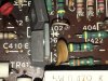
In your 5th pic I see one small thing that may deserve a closer look. There is a carbon film (tan) resistor partially hidden under a transistor. You can see only the left end of the resistor and orange and white bands. Perpendicular to those bands is a tiny black mark on the top of the resistor body. It looks like an eyelash kind of...it might possibly be a crack. I don't know. Check it out.
In your 4th pic with the scorch mark under a diode. My guess is that this was some type of one-time event. To me it does not look like sustained over heating. I have no explanation. I would verify functionality of that diode and the resistor next to it. And I would give more space between those two components as they both may (or may not) be heat producers.
As far as heat in general. Some resistors get hot. That is why some of them are large and mounted a significant distance off the board. In most cases it it nothing to worry about. Human touch, while valuable as an investigative tool (with proper caution), can not be used as an absolute guide to determine safe operating temperature of components. Often, something that seems very hot to the touch is operating within normal parameters. As a corollary to this topic, when you identify a hot running component, note whether there happens to be an electrolytic cap close to it. If so, that cap may be a candidate for upgrading to a 105C rated cap (most original caps are 85C rated).
Fusible resistors are a topic unto themselves. Some have a known tendency to increase in resistance value over time. This is well documented in Sansui amps. Reports of issues in Hitachi amps are also not uncommon. If I was refurbishing a Sansui or Hitachi, I would remove and replace all fusibles without a second thought. I am not sure I would automatically do that in a Technics or JVC. I would probably do some research first. I would search Audiokarma and DIYaudio for reports of issues. If there are none I would pull a couple of those resistors from each amp and test. You can't test resistors in place because there are often parallel paths which alter resistance readings. If those samples tested fine, and nothing found on the web (or the two specific sites mentioned) I would be inclined to leave them alone. All this last bit is my opinion of course.
In your first pic, R509 & R510 are carbon film. You could replace just R509 with carbon film, it would have a similar tan body color. Or you could replace both with metal film which will have a blue body. Pay attention to physical sizing. Small wattage resistors come in sizes of approximately 3mm, 6mm and 9mm. Don't stuff a physically larger resistor in a space where a smaller original had been, avoid bending the leg too close to the body of the resistor. You don't have to stick with 1/4w rating. Resistors with .5w and .6w are readily available. This is the part that I would use for R509 R510 https://www.mouser.com/ProductDetail/TE-Connectivity-Neohm/LR1F10K?qs=ip69W3eHERWDLLWs2Qv0Lg==
But you will have many options available. I don't know where you live. In the USA most of us go to either Digikey or Mouser. Both of them have wonderful search tools where you can dig through many parameters. A typical search would start like this: passive component >resistors> through hole resistors.... from there choose specific resistance value, body size range, and a range of power ratings from .25w to .6w. Always check the "in stock" box. Then click "apply filters" to see where you are. Narrow the search further as needed. You can also back your way out of a search as needed.
As for the other pics, all of the green and white resistors look OK to me. I would not change them.
In your 5th pic I see one small thing that may deserve a closer look. There is a carbon film (tan) resistor partially hidden under a transistor. You can see only the left end of the resistor and orange and white bands. Perpendicular to those bands is a tiny black mark on the top of the resistor body. It looks like an eyelash kind of...it might possibly be a crack. I don't know. Check it out.
In your 4th pic with the scorch mark under a diode. My guess is that this was some type of one-time event. To me it does not look like sustained over heating. I have no explanation. I would verify functionality of that diode and the resistor next to it. And I would give more space between those two components as they both may (or may not) be heat producers.
As far as heat in general. Some resistors get hot. That is why some of them are large and mounted a significant distance off the board. In most cases it it nothing to worry about. Human touch, while valuable as an investigative tool (with proper caution), can not be used as an absolute guide to determine safe operating temperature of components. Often, something that seems very hot to the touch is operating within normal parameters. As a corollary to this topic, when you identify a hot running component, note whether there happens to be an electrolytic cap close to it. If so, that cap may be a candidate for upgrading to a 105C rated cap (most original caps are 85C rated).
Fusible resistors are a topic unto themselves. Some have a known tendency to increase in resistance value over time. This is well documented in Sansui amps. Reports of issues in Hitachi amps are also not uncommon. If I was refurbishing a Sansui or Hitachi, I would remove and replace all fusibles without a second thought. I am not sure I would automatically do that in a Technics or JVC. I would probably do some research first. I would search Audiokarma and DIYaudio for reports of issues. If there are none I would pull a couple of those resistors from each amp and test. You can't test resistors in place because there are often parallel paths which alter resistance readings. If those samples tested fine, and nothing found on the web (or the two specific sites mentioned) I would be inclined to leave them alone. All this last bit is my opinion of course.
Last edited:
The values for all of the resistors in question may be verified using a meter. Over-current conditions causes resistors to overheat and the excess power dissipation, may alter the value but this is not guaranteed. Because resistors are not fuses, such over-current conditions may be long tolerated without failure for hours, even days, with the jacket cooked to the point of a severe alteration in color.
The cement-coated wirewound resistors will tolerate considerable heating without damage. As a guess I would surmise a voltage-divider to slightly adjust one of the supply voltages for regulation. Using a value such as 10 Ω permits current sensing using Ohm's Law. If the voltage drop across the resistor is known, then the current may be calculated as (I = E / R). That is speculation, and the schematic will prove invaluable.
I suggest walking back the circuit to find out, in not precisely how and why, at least a hypothesis as to circumstances giving rise to the over-current condition. Service manuals are very useful. It is possible that an electrolytic capacitor has either failed or is leaky which is passing too much current.
Given that a rectifier diode failed, excessive current is being drawn from the supply or the supply itself has failed, .I would expect a short in either a capacitor, or in an output device which turned fully on, dumping the rail to ground.
Great information! Thank you!
Will check diode if its working or not (have done it a few times). Amp does function great, but looking over I just noticed some parts that should be replaced.
Good pics @GytisB
In your first pic, R509 & R510 are carbon film. You could replace just R509 with carbon film, it would have a similar tan body color. Or you could replace both with metal film which will have a blue body. Pay attention to physical sizing. Small wattage resistors come in sizes of approximately 3mm, 6mm and 9mm. Don't stuff a physically larger resistor in a space where a smaller original had been, avoid bending the leg too close to the body of the resistor. You don't have to stick with 1/4w rating. Resistors with .5w and .6w are readily available. This is the part that I would use for R509 R510 https://www.mouser.com/ProductDetail/TE-Connectivity-Neohm/LR1F10K?qs=ip69W3eHERWDLLWs2Qv0Lg==
But you will have many options available. I don't know where you live. In the USA most of us go to either Digikey or Mouser. Both of them have wonderful search tools where you can dig through many parameters. A typical search would start like this: passive component >resistors> through hole resistors.... from there choose specific resistance value, body size range, and a range of power ratings from .25w to .6w. Always check the "in stock" box. Then click "apply filters" to see where you are. Narrow the search further as needed. You can also back your way out of a search as needed.
As for the other pics, all of the green and white resistors look OK to me. I would not change them.
In your 5th pic I see one small thing that may deserve a closer look. There is a carbon film (tan) resistor partially hidden under a transistor. You can see only the left end of the resistor and orange and white bands. Perpendicular to those bands is a tiny black mark on the top of the resistor body. It looks like an eyelash kind of...it might possibly be a crack. I don't know. Check it out.
In your 4th pic with the scorch mark under a diode. My guess is that this was some type of one-time event. To me it does not look like sustained over heating. I have no explanation. I would verify functionality of that diode and the resistor next to it. And I would give more space between those two components as they both may (or may not) be heat producers.
As far as heat in general. Some resistors get hot. That is why some of them are large and mounted a significant distance off the board. In most cases it it nothing to worry about. Human touch, while valuable as an investigative tool (with proper caution), can not be used as an absolute guide to determine safe operating temperature of components. Often, something that seems very hot to the touch is operating within normal parameters. As a corollary to this topic, when you identify a hot running component, note whether there happens to be an electrolytic cap close to it. If so, that cap may be a candidate for upgrading to a 105C rated cap (most original caps are 85C rated).
Fusible resistors are a topic unto themselves. Some have a known tendency to increase in resistance value over time. This is well documented in Sansui amps. Reports of issues in Hitachi amps are also not uncommon. If I was refurbishing a Sansui or Hitachi, I would remove and replace all fusibles without a second thought. I am not sure I would automatically do that in a Technics or JVC. I would probably do some research first. I would search Audiokarma and DIYaudio for reports of issues. If there are none I would pull a couple of those resistors from each amp and test. You can't test resistors in place because there are often parallel paths which alter resistance readings. If those samples tested fine, and nothing found on the web (or the two specific sites mentioned) I would be inclined to leave them alone. All this last bit is my opinion of course.
Thank you for the recommendation on parts! I have to measure the size before ordering.
I live in Norway (updated my location now), so I do use Mouser for ordering stuff. There is nothing/not much I can get here, so it has to be somewhere from internet. I ordered once from Mouser, when recapping Sansui AU3900 (first recap I ever did), and I was very statisfied with the Mouser parts. Might try DigiKey sometime.
I will check the resistor on the pic 5. Didn't notice the crack/damage before you mentioned it.
EDIT: I will stick to the DigiKey this time. Can’t find all the parts I need at the Mouser this time (they are there, but not in stock, and it might take weeks/months before they get them). Since I have a few other projects coming and need extra stuff. Hope to find everything there. I might need to mix and match some. Noticed DigiKey has a bit higher prices too, like a few cents extra per part.
Last edited:
I placed an order on the DigiKey earlier this day. Didn't order "too much" or stuff that looks good as all of you said, not looking for problems (in case something would break, it would be easier to find out what to check). Got some film resistors that @roger2 recommended. Price was ok, and specs looked great too. Got also replacement for the R423 and R424 (the one in the pic 5, and one the same at the other side), since it looked bad. Bought some electrolytics for the recap (2-3 amps). Ended up with a pretty big/expensive order, I hope I will be statisfied . Thank you for the help.
. Thank you for the help.Sounds good @GytisB. Let us know how things work out.
Will do!