You are using an out of date browser. It may not display this or other websites correctly.
You should upgrade or use an alternative browser.
You should upgrade or use an alternative browser.
Restoring and Cleaning Amplifier Internals

Do you have it working yet? I would not be un-wrapping those wires until you've got it fully operational. Save cleaning for after it's working as intended. Still no evidence that those posts are causing any issues...?
Mike
Yeah it works! I got the dim bulb tester in the power circuit and it's running without a short on all inputs and channels. Just learned how to test dc bias earlier, but I can't test it because the speaker terminals are rustler than the tin man in oz.
I just finished making a wire dewrapper out of an old antenna. It sounds weird, but I documented it with video. I'll post a youtube video in a couple days.
The posts are good contacts, but I'll probably get the blue display and pcb off without much messing around on other wire wraps. The display is connected by about 8 wire wraps. That's all I'll probably mess with. Get the sensitive equipment off and do some TLC on the remaining. I'm excited, this will be a good experiment.

Nice recovery. You might consider daubing the wire wrap pin connections near the tips with acid flux (the type used for silver brazing) then tinning - soldering the connections lightly. Neutralize the acid with a soda/water solution after soldering, them rinse with clear water, and dry / rinse with isopropyl alcohol.
The acid flux may also be useful for the RCA jacks and speaker terminals, but be certain to neutralize and rinse thoroughly.
The acid flux may also be useful for the RCA jacks and speaker terminals, but be certain to neutralize and rinse thoroughly.

RTally
Speaker addict
Nice recovery. You might consider daubing the wire wrap pin connections near the tips with acid flux (the type used for silver brazing) then tinning - soldering the connections lightly. Neutralize the acid with a soda/water solution after soldering, them rinse with clear water, and dry / rinse with isopropyl alcohol.
The acid flux may also be useful for the RCA jacks and speaker terminals, but be certain to neutralize and rinse thoroughly.
DON'T DO THAT! Only use rosin flux for electrical work.
Acid flux should never be used with electrical connections. Acid flux will do a very good job of cleaning the surfaces. But the residue will kill your PCB and components, no matter how good you think you can clean them. This is particularly true for soldering wire wrapped connections. The small spaces will trap the acid flux. It may work fine at first, but down the road there will be problems.
Granted, very experienced and skilled persons with the proper equipment may be able to use and clean up acid core flux, but those with less than super-expert skills should avoid it. Rosin works. There is never a need to use acid flux for standard, copper-based electrical connections.

Scott75s1974
Well-Known Member
My understanding is that wire wrap connections create a very airtight bond on the corners of the posts, which are much more robust than the outside would have us believe. So, don't assume they are faulty based on exterior corrosion.
I've looked into various molex connectors and it seems they require very specialized and _astoundingly_ expensive crimpers that are much more trouble then they are worth for any single instance use.
I've looked into various molex connectors and it seems they require very specialized and _astoundingly_ expensive crimpers that are much more trouble then they are worth for any single instance use.
Thanks guys for all the suggestions. I've been documenting the clean up while doing another project at the same time, so it has taken time. Right now I've got the VFD/flouroscan off and protected away. This was after I made my own wire wrap remover. I'll leave the rest of the wire wraps intact.
The flouroscan cathode points were a circular toasted black, but it was working correctly when it was removed.
Interesting breakthrough! Molex square ATX or PCI-E (depends where the end connection will end up) female header pins fit perfectly onto these wire wraps. Which is really cool if anyone ever restores and wants to recreate easy wire removal. The square molex tangs that hold the header in the plastic would have to be squeezed inward.
Here's some pictures.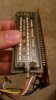

The flouroscan cathode points were a circular toasted black, but it was working correctly when it was removed.
Interesting breakthrough! Molex square ATX or PCI-E (depends where the end connection will end up) female header pins fit perfectly onto these wire wraps. Which is really cool if anyone ever restores and wants to recreate easy wire removal. The square molex tangs that hold the header in the plastic would have to be squeezed inward.
Here's some pictures.
That was probably like that when new.he flouroscan cathode points were a circular toasted black, but it was working correctly when it was removed.
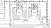
I am pretty much done, and putting it all back together. I am about to check the DC bias, but I have a problem. I marked one of the ground wires to differentiate as L/R and I'm pretty sure its R, but not 100%. If the amp is common ground it shouldn't matter anyway right? Here is the schematic, and the L/R connect to ground pins 10 and 11.
Would it matter if I connected incorrectly?
Would it matter if I connected incorrectly?
Attachments


This thing is running nice. I got 6.4mV bias on R and 10.1mV on L. I'm going to close the chassis and start using it.
I used the same ground on the bias adjustments. I'm going to put the ground pins back how I think they were on L and R. Since it looks common on the schematic, i dont think it'll be a problem if i accidentally switch them.
The rear was absolutely rusted with total loss of input markings, so I needed to reprint the markings. The speaker terminals were rusted beyond repair as well. I made a makeshift banana plug inputs. I'll post a pic when the ink is dry. For the purists, it definitely looks different than stock.
New updated thermal grease, cleaned of flux, and a washed circuit board. Overall it did well. It still smells acidic, but oh well. I sprayed the crap out of that thing.
Pictures and videos soon.
I used the same ground on the bias adjustments. I'm going to put the ground pins back how I think they were on L and R. Since it looks common on the schematic, i dont think it'll be a problem if i accidentally switch them.
The rear was absolutely rusted with total loss of input markings, so I needed to reprint the markings. The speaker terminals were rusted beyond repair as well. I made a makeshift banana plug inputs. I'll post a pic when the ink is dry. For the purists, it definitely looks different than stock.
New updated thermal grease, cleaned of flux, and a washed circuit board. Overall it did well. It still smells acidic, but oh well. I sprayed the crap out of that thing.
Pictures and videos soon.
Well, bad news. I set it up and turned it on, but the audio is leaking through all the inputs. I change each input and I can hear the audio terrible and quiet through all. The phono inputs are corroded, so I switched between them all, but something is happening on the board.
Does it need a recap? Where should I go from here? Should I make sure the BJTransformers outputs arent shorted?
Symptoms. The audio is quiet like background crosstalk. a little pot jump with static audio spike at 5 o clock on volume. A/B works as intended and blocks off signal. No volume/wattage registration on the display. Spike at volume pot specified earlier. I will hear some quiet audio at 80% volume and no register on the display.
Shoot! I spent hours cleaning it up, but I should have checked speaker function!
Do I need to recap? Should I touch up solder joints? I saw a advil cap with the coating flaking off. Is it salvageable?
Does it need a recap? Where should I go from here? Should I make sure the BJTransformers outputs arent shorted?
Symptoms. The audio is quiet like background crosstalk. a little pot jump with static audio spike at 5 o clock on volume. A/B works as intended and blocks off signal. No volume/wattage registration on the display. Spike at volume pot specified earlier. I will hear some quiet audio at 80% volume and no register on the display.
Shoot! I spent hours cleaning it up, but I should have checked speaker function!
Do I need to recap? Should I touch up solder joints? I saw a advil cap with the coating flaking off. Is it salvageable?
Thanks watthour.
There is the ground wire to the chassis that looks like it's in poor shape. I'll touch it up and see. I got good continuity with a dmm so I figured it was fine.
I think the problem is before the output bjt transistors. I tested them and they seem fine. I do get a little diode reading reversed at collector and base, but it is uniform across all 4, so I think it's the transistors sitting in circuit.
I wonder if I should get an esr meter. I think there are 25 caps total?
I also got normal audio on tape 2 setting, but no real reading on the amp display meter.
EDIT: Tape 2 setting works fine with audio and amp decibel meter. Tape 2 is a physical switch on the bottom. So I am leaning toward a grounding issue with the tuner/phono/aux/tape 1 chain.
There is the ground wire to the chassis that looks like it's in poor shape. I'll touch it up and see. I got good continuity with a dmm so I figured it was fine.
I think the problem is before the output bjt transistors. I tested them and they seem fine. I do get a little diode reading reversed at collector and base, but it is uniform across all 4, so I think it's the transistors sitting in circuit.
I wonder if I should get an esr meter. I think there are 25 caps total?
I also got normal audio on tape 2 setting, but no real reading on the amp display meter.
EDIT: Tape 2 setting works fine with audio and amp decibel meter. Tape 2 is a physical switch on the bottom. So I am leaning toward a grounding issue with the tuner/phono/aux/tape 1 chain.
Last edited:
I think I figured it out, but I need you guys help! A transistor is giving fully open diode readings on the phono preamp or eq (im not sure which.) Even if I switch off phono to aux it wont work unless I bypass the tuner/phono/aux/tape1 by switching to tape 2.
I'm still very new at this. Can a blown transistor short out a circuit to ground and cause these issues? I'd probably need to replace all right? Should I replace the phono preamp caps as well?
EDIT: Also, what if I take out the transistor or the pair and see if it works then?
I'm still very new at this. Can a blown transistor short out a circuit to ground and cause these issues? I'd probably need to replace all right? Should I replace the phono preamp caps as well?
EDIT: Also, what if I take out the transistor or the pair and see if it works then?
Last edited:
I got it working. It was the ribbon slider switch which as all rusted inside. I found some information from this website. https://hoppesbrain.com/2017/06/01/...555-and-gfp-565-record-and-playback-switches/
Here's a pic of what it looked like.
And here is the restored back. It is the best I could do with my skills at this time. Its unfortunately not stock looking, but the amp is not in the trash as well. So a plus for the amp.
Thanks all for the help. I really appreciate it. I learned a huge amount. I'll put together a youtube vid in the coming weeks.
Here's a pic of what it looked like.
And here is the restored back. It is the best I could do with my skills at this time. Its unfortunately not stock looking, but the amp is not in the trash as well. So a plus for the amp.
Thanks all for the help. I really appreciate it. I learned a huge amount. I'll put together a youtube vid in the coming weeks.