• The move to the new server is done. There are some software and database maintenance updates in process. This has us passing the hat around to help out. We appreciate any donations. Seriously, even a dollar helps. The payment page may be found here - https://www.audiokarma.org/support.html

Restoring & modding a Marantz 3800

Numistrek09

Super Member
Ok folks, here is my long promised post about overhauling a Marantz model 3800 pre amp. Much of this info can be used on the 3600 as well. I'm not much of a writer, but i have tried to make this clear and simple to follow. Hopefully it is not too wordy or excessive to understand. If you wish to follow in my footsteps, you can do some of this, all, or none.

Back story . . .

The 3800 has been my pre amp for a number of years now. It was Marantz's TOTL unit in 1975, with a list price of $600 dollars, according to these guys:

http://www.classic-audio.com/marantz/3800.html
(Specs listed there as well.)

I've always liked the looks of this unit and found it to be very functional. But as it has aged, it has gotten noisier and more intermittent with the controls. By last spring, i was having to tap on the knobs routinely to keep the signal passing. Thinking that it may only need a deoxit bath, i pulled it from the rig to give it a good cleaning. This should have been simple enough, but it wasn't. Upon opening the hood, not only did i find dirty controls, (some so bad as to be almost black) i found some bulging caps as well. The time had finally come to do a restoration. I had been putting it off until i was more experienced with electronic repairs. But after seeing the condition of the caps, i felt it couldn't wait for me any longer. So i began a months long research project to learn all i could about the 3800 and what others have done to it during their restorations. After hours of searching on AK, i didn't find a lot actually. The few posts by those who have restored their units were rather vague. Most posts only discussed issues with the op-amp chip inside, and it's near impossibility to find. (More on that later.) So i looked at other related threads for inspiration. I also carried on lengthy conversations with several of Aks best techs, including Marantz specialist Catrafter. After several months of reading, shopping, and planning, i was as ready as i would ever be. In the end, i decided to not only restore the unit, but make a few carefully selected upgrades as well. And i have kept track of my every move with pictures so i could make this post. Hopefully it will help someone else seeking to do the same.
 
Register to hide this ad
All I can say is, lets have it! :)

I'll be watching this one. I have never seen inside a 3800 pre before.

:lurk:

Good luck. ;)
 
Section 1: Getting started

I found out that you don't need very many specialized tools to work on one of these. There are only a couple of things that a servicer can adjust. Most of the Service Manual is just tests to confirm that the unit is performing correctly. So if you have a scope, a good DMM and a signal generator, you are pretty much set. (Of course, more stuff is better.) I also happen to have an AC millivolt meter, which did prove useful for channel balance and output level tests. The 3800 contains fifty-four electrolytic capacitors, of them eight are axial type. For replacements, i choose the highly regarded Elna Silmic IIs for the radials and Vishey ASM 021 for the axials. Now i know some folks might just shoe-in radials in those positions, but i don't like the way that looks very much. And the Vishey's are considered to be good, low ESR parts. So i saw no good reason not to use them. I also heeded Catrafter's suggestion to replace all three of the X2 safety caps. Now comes the part where i went beyond just restoring and into tweakers territory. I decided to ditch all of the monolithic film capacitors for modern polypropylene types. From all of my reading, it seemed like this would be a good bet for improved
sound. I also decided to dump the carbon composition resistors on the headphones jack and replace with metal oxide.

I first looked at the well thought of Wima line of polypropylenes as my new film cap. But i found it difficult to locate all the values i needed with the correct lead spacing. So instead i went with a line of polyprops that Echowars recommended to me, Panasonic's ECW-F series. With these i easily found all the values i needed and with the correct lead spacing. They look nice too, like little bits of red candy. There was one problem though, they aren’t available in values below .01uf. I suppose i could have left the old films in place for these positions, or used silver micas. But i still wanted to try and upgrade and have read that you should replace "like for like". There was still another type of film cap i could try, polystyrene. This took a little bit more searching to locate parts of the right size and value, but i did find them without too much fuss. Below is my list of parts that i replaced and their values:

Quantity Value Type Axial/Radial Digikey Replacement #
2 1,000pf Film A N/A
4 1,500pf Film A N/A
4 4,700pf Film A N/A
10 5,600pf Film A N/A
2 .022uf Film R P12059-ND
10 .027uf Film R P12063-ND
4 .047uf Film R P12075-ND
12 .1uf Film R P14194-ND
3 .15uf Film R P14242-ND
2 .22uf Film R P14244-ND
4 .33uf Film R PCF1576-ND
6 1uf Film R P13744-ND
8 4.7uf 25V Electrolytic R 604-1049-ND
19 10uf 16V Electrolytic R 604-1109-ND
6 10uf 25V Electrolytic A 4211PHCT-ND
10 22uf 25V Electrolytic R 604-1052-ND
2 47uf 25V Electrolytic R 604-1054-ND
1 47uf 50V Electrolytic R 604-1127-ND
6 100uf 16V Electrolytic R 604-1110-ND
2 100uf 25V Electrolytic A 4032PHCT-ND
1 470uf 16V Electrolytic R 604-1116-ND
2 470uf 63V Electrolytic A 4079PHBK-ND
3 10,000pf X2 Film R P10724-ND
2 330ohm Metal oxide resistors 330W-1-ND

Notes:

1: The 1,000, 1,500 and 4,700pf components came from http://www.westfloridacomponents.com/. I wound up using the radial version of the 4,700pf, instead of axial due to lead spacing. The 5,600pf styrenes came from ebay and were Philips branded.

2: I ordered replacements for all three .15uf film caps, but did not use one as the original was in the power supply.

3: Two of the 22uf 25V electrolytics were upgraded to 47uf 25V by Marantz, in units with serial numbers after #3276. I decided to do this to mine as well, but ordered the two extra 22uf caps just in case.
 
Section 2: Disassembly and cleaning, part 1

Taking the 3800 apart is pretty easy, actually. All the major PCBs fit together with pin connections. So once all the nuts and screws are released, you can pull the circuit boards apart; (gently of course). Many of these pins were dirty with age. I started by examining two of the most problematic of the controls; the tape selector and Dolby switch. Both are attached to the Dolby PCB and are made up of several wafers with silver contacts. The tape selector wasn't great, but it wasn't as bad as the Dolby switch. It was almost completely black on several of its wafers. I thought for a while about how best to try and clean all of these contacts. I suppose i could have soaked them in deoxit, but i thought that would make a mess all over the board below. Moreover, this was some heavy oxidation. So i decided to take a more radical approach. NOW THIS IS NOT A PROCEDURE FOR THE FAINT OF HEART, and is SOOO easy to screw up if you're not careful!!! But fortunately, i am a bit OCD and crazy enough to document everything and not lose exceedingly small parts. I decided to take the multi wafer switches apart, un-solder them from the PCB, and clean them directly. (I told you i was crazy.)

The tape selector switch was easiest, only two wafers with contacts on one side. It's held together with two screws fed through metal spacers and some insulating washers. In the back are more washers and a nut to hold it all together. First you remove the nut and stacked washers behind it. One is metal, i'm not sure what the other washers are made of, but they look fragile so be careful. Plus, they are ridiculously small. Now you can slowly start pulling out the screw. Soon you can remove the first metal spacer and the next single washer. Then as it clears the front of the wafers, you can remove the next washer and the final spacer. Repeat on the other side. Now pull out the part with the knob shaft, and the long rod that actually moves the contacts on the wafer. While still in place, it is a good ideal to mark which wafer is front and back. I used a pencil on the top, one line for the front, two for the back. Time to un-solder. I found these double-sided PCBs were not as easy to work with as other examples. So take care and eventually you should be able to remove the wafers. Now mark the position of the rotating part with a sharpie, to show which way to orient it when reassembling. This is very important if you wish to avoid headaches later. Now move onto the second wafer and repeat.

Next is the Dolby switch. This one is much more complex, as it has contacts on both sides of all four wafers! However, it comes apart pretty much the same way. Begin by removing the nut on the back of the screw and the stacked washers. Then start backing the screw out and collect each spacer and washer as they become free. Section by section you go, until you reach the forward most washer and spacer. Then you repeat on the second screw. Now remove the key, or whatever they call the shaft in the middle that actually turns all this stuff. Use the same top side numbering as before. I II III IIII, front to back. Un-solder the pins and remove the wafers. This is a bit harder on the Dolby switch, as some of the pins are quite close to parts on the tone/VU board. It would be easy to let your iron hit the big plastic wheels of the adjustment pots, but these wheels can be pulled off if you are afraid of hitting them. They pop back in once done. Now, as with the tape selector switch, sharpie the correct orientation of each of the rotating parts before proceeding.

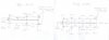
Below are drawings i made to show how these switches come apart and what pieces go where.
 

Attachments

  • Switch diagrams.jpg
    Switch diagrams.jpg
    21.1 KB · Views: 134
Once all six wafers are free, time to get some liquid silver dip. Take hold of each wafer with some needle nose pliers and dip into the silver cleaner for maybe five seconds. Then remove and rotate with a stick, or small screwdriver, the part that moves. Be sure to get all areas exposed to the silver dip. Then stick back in the dip for a couple more seconds and remove. Shake off and put into a bowl of water to neutralize the dip. Rinse really well in water and then toss into a bath of high grade IPA. This will displace anything left behind by the water or dip. After a few minutes, remove and allow to fully dry. Once dry, apply some Deoxit gold to the main rotating contact surface and spin it around to get it on all of the little "fingers." Once you are finished with this, clean the pads on the Dolby board to prep for re-soldering. I also added some new lithium grease to the gear and ball on the selector switch rotators themselves. Once everything is good to go, set the wafers back into their correct locations and loosely reassemble the switches. You want to do this while the wafers are not soldered back in yet, so as to be sure all wafers are vertical and won't stress the new solder joints. You don't have to fully tighten up the screws yet, just make them tight enough to hold the switches together. Now re-solder. Once done, tighten up the screws and nuts. But not too much, as i imagine those insulator washers will probably break and fall away.

Note:

When i did this, i did have a pin break on one of the wafers. Not sure if it was damaged to begin with, or failed during my removal procedure. In any case, if this happens to you, here's how i delt with it. I un-soldered and removed the broken end of the pin from the wafer board. Then i took a lead, left over from a previous recap, and fit it through the pin hole on the wafer. I bent one end down inline with the remaining pins, and bent the other end up until it was flush with the trace on the wafer. Trimmed it to fit and soldered the lead to the trace. I then checked for any solder bridges to the adjacent traces, (they are close together) and trimmed the excess off the bottom of the new "pin." This repair worked perfectly for me and gave no issues when re-soldering the wafers back in place. It looks barely noticeable as well, so i'm pleased with it.

Below are pictures of the switch contacts before and after the silver dip.
 

Attachments

  • Switch contacts 1.jpg
    Switch contacts 1.jpg
    90.5 KB · Views: 198
  • Switch contacts 2.jpg
    Switch contacts 2.jpg
    73.7 KB · Views: 173
  • Switch contacts 3.jpg
    Switch contacts 3.jpg
    52.3 KB · Views: 158
  • Switch contacts 4.jpg
    Switch contacts 4.jpg
    71.4 KB · Views: 168
  • Switch contacts 5.jpg
    Switch contacts 5.jpg
    86.2 KB · Views: 173
Section 2: Disassembly and cleaning, part 2

After the tape and Dolby switches, i went onto the mode control. This was much easier to take apart and clean. All i had to do was undo the screws holding the knob shaft to the circular contact piece. They are removed from the back of this switch, unlike with the Dolby or tape switch. There are a couple small white plastic washers and spacer bars to capture during the dismantling. Once apart, unsolder the "works" of the switch, mark which way is up, and give it the same silver bath treatment i described above. Then soak in water, shake out excess, soak in IPA and dry. Finally, spray in through the gaps of the plastic covering the contacts, some deoxit gold and spin it all around. And just like with the other two switches, i added some new grease to the ball and gear of the rotator itself. Once everything is dried and lubed, re-solder the contact "ring" to the control PCB and reattach the rotator. Done! Now it gets scary again, because the volume pot, Dolby level pots and all those sliders, are next. These probably could have been cleaned in the standard way. Just spray in some deoxit and turn a bunch of times, then repeat. Or spray them down with faderlube and move the sliders up and down. But i know this often ruins that smooth feeling in pots and sliders, and it can take several times to get right. So here comes another over the top procedure in the fine pursuit of overkill.

I began by breaking the thread locker seal, which holds the screws down on the connector plate joining all the sliders together. (partially visible in picture 1) Then i undid the screws keeping the VU meter in place and slipped the power-on light out of its groove. There is some tape that goes over the VU meter light wires. This tape looks like it used to have some foam attached to it, but that has since all crumbled away. Just pull this tape off and remove the metal brace. You'll have to pull the VU meter through the brace to get it completely free. Now you have access to the sliders directly. The left treble slider has a piece of blue cardboard slipped under it and up between it and the VU. I guess it is an insulator. No problem, as it comes out easily from under the slider. Since all the tone sliders are of the same value, i un-soldered them all at once. The balance pot is visibly different, so it can't be confused with the others. Then i removed the Dolby pots and volume control. With all these parts removed, now is a great time to recap. There are four 10uf 25V axials here, (also partially visible in pic 1) as well as two of the monolithic film caps. The service manual lists them as 3,600 pf, but i found 5,600 pf was used in my unit. So i replaced with styrene caps of the value installed. The service manual had another discrepancy with this PCB as well. It says that the Dolby record pots are 50kohms and the Dolby play pots are supposed to be 25kohms. In my unit, all were only 25kohms. I'm not sure if this is a mistake in the manual, or at the factory that built it. Either way, i left it as is.
 

Attachments

  • Slider plate.jpg
    Slider plate.jpg
    76.5 KB · Views: 205
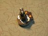
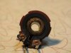
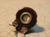
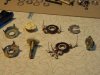
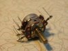
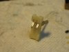
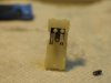
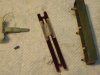
Now back to the cleaning. I decided to start with the Dolby pots, as they were the least important if i screwed things up. To get them open, you have to lift the four tabs on the front that hold it together. (pic 1) I did this by taking a wide bladed exacto knife and wedging it under one of the tabs. (pic 2) Slowly and gently i started lifting the tab until it was high enough to get a flat head screwdriver under. Once i reached this point, it was easy to raise it completely upright. (pic 3) Keep your finger on the backside of the tabs while raising, to help control how fast you lift and keep from over extending them. After you lift the last tab, the pot kinda "pops" open. The resistive part comes out on top and leaves the rest behind. (pic 4) The center leg of the pot does come loose and is attached to a brass ring in the center of the carbon trace. If this falls out during disassembly, don't panic, it just sits back into place. The pot shaft is connected to a piece of plastic that holds brass contacts on it. These contacts are what slide around on the carbon trace and connect to the brass ring sitting in the front piece. There is no oil or dampening grease in the pot shaft sleeve, least, i saw no evidence of it. Instead, the smooth feeling is created by dampening grease in the back of the pot casing, where the plastic base rotates. You can see the internal construction of the pot and this grease from picture 5. I don't have many values of dampening grease on hand, (also know as differential fluid), so i tried what i did have and settled on 1,000 cst. This gave a nice smooth rotation. For an even smoother movement, you may wish to try 1,500 or 2,000 cst. To apply, just wipe off most of the old grease and add four small drops of the new to the edge of the plastic backer. Then reseat into the pot casing and spin it around a few times to spread the grease evenly. Now we clean the contacts. I took some deoxit and sprayed it on a q-tip, and gently cleaned the contact fingers on the brass of the pot shaft. Then i cleaned the brass ring that sits in the resistive wafer. This was the dirtiest part. I used both ends of the q-tip to get this one part clean, and i had to do that in all four pots! See before and after (pics 6 & 7) Next i took a q-tip soaked in faderlube and wiped down the carbon trace. This also dirtied my q-tip a little, but not as badly as with the grounding ring. I could turn the q-tip and use the back side and be fine. It also left a nice coating of faderlube on the trace. Now i could reassemble the pot. Not much to describe here, just slide the carbon wafer back onto the pot shaft and hold it down into its "seat.” Then use the flathead screwdriver to gently bend the tabs back over one at a time. First rotate them over, then press down on them firmly to make sure everything is tight. Waa la, you're done!
 

Attachments

  • Pot 5.jpg
    Pot 5.jpg
    44.1 KB · Views: 108
  • Pot 4.jpg
    Pot 4.jpg
    54.8 KB · Views: 110
  • Pot 3.jpg
    Pot 3.jpg
    47 KB · Views: 97
  • Pot 2.jpg
    Pot 2.jpg
    49.2 KB · Views: 99
  • Pot 1.jpg
    Pot 1.jpg
    46.5 KB · Views: 102
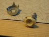
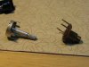
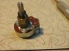
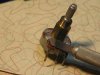
How about the volume pot? (pic 1) Ok, we can do that too. Start off by lifting the four hold down tabs just as i described above. The brass part with the nut threads will lift off first, then you can lift off the resistive wafer. The brass center leg/ring piece can come loose with this pot as well. Next, grab the pot shaft and pull. It will lift out and remove the part that rotates the lower portion of the pot as well. (pic 2) Now the more difficult part. You must raise the tabs holding the upper pot shell to the lower one. This can take some fiddling, but eventually i was able to get enough lift on the tabs to finish raising them with the screwdriver. Now with the top section removed, repeat the usual tab lifting step to open the lower section. Lift off the metal U-shaped piece, then the resistive wafer. (pic 3) Finally, pull out the rotating part inside. This is how the pot looks fully dismantled. (pic 4) Now we repeat the clean up steps i did for the Dolby pots. Add dampening grease to the back of the plastic rotator, clean brass fingers and brass ground ring, then faderlube the carbon trace. Once you have done this, you can reverse the dismantling process and reassemble the pot. There is one thing to note, make sure to put the U-shaped ring that goes on the lower section back on correctly. The open part faces the legs of the pot. Putting it on upside down allows it to touch the grounding leg and then the whole left channel casing becomes grounded. That is not how it's supposed to be!
 

Attachments

  • Volume pot 4.jpg
    Volume pot 4.jpg
    68.9 KB · Views: 137
  • Volume pot 3.jpg
    Volume pot 3.jpg
    67.9 KB · Views: 117
  • Volume pot 2.jpg
    Volume pot 2.jpg
    60.4 KB · Views: 123
  • Volume pot 1.jpg
    Volume pot 1.jpg
    46.4 KB · Views: 127
Section 2: Disassembly and cleaning, part 3

The sliders, like the pots, are held together by tabs on the back. (pic 1) These are also easy to lift with the exacto knife. Once all are lifted, the back of the slider comes off and exposes the silver contact fingers and the innards of the control. Now these guys have some easily lost small parts inside, so have a paper towel underneath to catch any roll away items. With the open slider sitting on the towel and the ridged section of the frame facing down, gently push the slider through the frame until it is free. Then lift it up and revel the now loose small parts. There is a very small ball and spring that sits in a hole on the plastic slider. This is what makes that clicking sound as you move it up and down its range. The ball is catching on the grooves in the slider casing. You can see them in the next pic. (pic 2) The next step is to push the white H-shaped slider and the mica(?) track out of the metal framework. (pic 3) This mica track isn't glued in or attached in any way, it just sits inside the housing. It is between these two parts that the slider dampening grease is applied. Wipe both the track and the slider clean and set them aside. Now we get out the silver dip again and dip the arm piece with the silver contacts. Same amount of time, same clean up as with the selector switches. You don't need to dip the whole works, just the part with the fingers attached. You can see how they looked before (pic 4) and how they look after (pic 5). Much nicer. After this i did the same type of clean up on the carbon track as i did for the Dolby pots.
 

Attachments

  • Slider 5.jpg
    Slider 5.jpg
    39.3 KB · Views: 109
  • Slider 4.jpg
    Slider 4.jpg
    28.9 KB · Views: 111
  • Slider 3.jpg
    Slider 3.jpg
    61.2 KB · Views: 117
  • Slider 2.jpg
    Slider 2.jpg
    53.2 KB · Views: 102
  • Slider 1.jpg
    Slider 1.jpg
    58.7 KB · Views: 107
Reassembly:

First up, put the long track back into the metal housing and apply four drops of the 1000 cst dampening grease to the four corners of the H-shaped slider. Then carefully drop it onto the middle of the track and slide it up and down the full travel path. This did a nice job of spreading out the new dampening grease evenly. (pic 6) Now turn the housing on it's side and start to put the slider arm piece back through the white H slider. When the main body of it is near to going back into the metal housing, put the spring back into its hole and seat the ball on top. (pic 7) Trying to get it to go back into the housing, without the ball popping out or falling off, was the hardest part. After a couple tries, i got it back together by lining up with one of the ridges and holding the ball down with my screwdriver as i pushed everything into place. Once back in, the slider clicks into each groove as usual. (pic 8) Then all i had to do was reseat the resistive backer and fold the tabs over. This is made easier if you move the slider all the way to one end, and bend down the tabs of the opposite end first. This way you can rest the slider on the edge of the desk and apply good pressure and still not damage anything.
 

Attachments

  • Slider 6.jpg
    Slider 6.jpg
    57.7 KB · Views: 73
  • Slider 7.jpg
    Slider 7.jpg
    38 KB · Views: 65
  • Slider 8.jpg
    Slider 8.jpg
    50.5 KB · Views: 65
With all the sliders, pots and selector switches done, i moved onto the push switches. In my unit these were the only ones that were quiet to operate, but i still wanted to check them anyway. This type of work is already fully and beautifully described by AKer, Leicalover, in the following thread:

http://www.audiokarma.org/forums/showthread.php?t=266269

I got lucky here, upon opening all of the push switches i found none that were dirty or tarnished. It seems whatever grease they used in there protected the contacts. So i just reassembled and let them be. After that i moved onto the RCA jack plate. This comes out as one big soldered piece. (pic 1) I wanted to upgrade the jacks to gold ones before i knew this, but decided to leave it as is after i saw how it was constructed. (pic 2) Since i was now keeping the original jacks, i would have to clean them. I took a bit of a scotch bright pad and cut it to fit inside the socket end of a nut driver. I then sprayed the pad with deoxit and slid it onto the jacks and started turning. This did a good job cleaning up the outside of the jacks. I read about someone here doing a similar trick to his RCAs, but he used Brasso instead. So i suppose you can do either/or. Next i took a q-tip with the soft cardboard type stick, and cut one end off. Then i sprayed deoxit inside each of the jacks, stuck the cardboard end of the q-tip in and spun/pushed-pulled until clean. I went through a couple of q-tips this way, as the stick became quite dirty half way through. Once all was done, i sprayed some deoxit gold inside the jacks and applied some to the outside with another q-tip. I also treated the two pins that connect by wire to the Dolby board. These are the main pre out connections, so don't forget to clean them. The same goes for the pins on the Dolby board where the wires attach.
 

Attachments

  • RCA 1.jpg
    RCA 1.jpg
    69.3 KB · Views: 122
  • RCA 2.jpg
    RCA 2.jpg
    86.7 KB · Views: 128
Section 3: Recapping

Replacing the electrolytics was pretty straightforward and is a well-documented process here. I did the front control board first, then the Dolby board, the tone/VU board, and finally the pre amp board. The Dolby board was the hardest, because the lead holes seemed to like getting clogged when i would pull a cap out. So i would have to reheat them and suck out the clog, or push it through with the new caps leads. But all turned out ok. After finishing up with the electrolytics, i set about replacing the film caps. This went about as smoothly, though a little lead bending was in order on a few. Mainly the polystyrene caps, as most were axial instead of radial. The only ones that gave me any real issue were the 5,600 pfs, because they were a little longer than the lead holes. I had to stand them up a little off the board and bring the leads back under. They still sit no higher than any of the other parts on the boards, but i would rather have found a nice radial or smaller axial version to get a closer fit.

Notes:

I found more discrepancies with the service manual during the recap. C231's polarity is not marked on the PCB layout page. The + side faces the + of C232. Also, the main schematic diagram is wrong for C703 of the VU circuit. It is shown reversed there, while on the PCB layout page it is shown correctly. There is also a jumper not shown on the pre amp board layout.

Images of recapped boards:
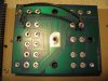
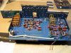
1 & 2 are of the recapped Dolby board. You can also see the reassembled selector switches.
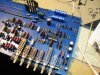
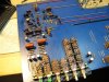
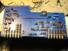
3 - 5 are of the recapped pre amp board.
 

Attachments

  • Recapped 5.jpg
    Recapped 5.jpg
    108.2 KB · Views: 231
  • Recapped 4.jpg
    Recapped 4.jpg
    92.3 KB · Views: 206
  • Recapped 3.jpg
    Recapped 3.jpg
    95.1 KB · Views: 212
  • Recapped 2.jpg
    Recapped 2.jpg
    108.3 KB · Views: 214
  • Recapped 1.jpg
    Recapped 1.jpg
    107 KB · Views: 246
Last edited:
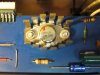
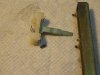
Next i replaced the AC safety caps on the chassis itself. You must remove the metal shield and blue cardboard insulator to gain access to the one on the power switch. For replacements, i used Panasonic ECQ-U2A103ML. While i had access, i also replaced the carbon composition resistors connecting the headphones jack to the speaker on/off switch. At this point, the resistors were the only thing holding the headphones jack on. (pic 1) So i took care in un-soldering and detaching them, that way i could use them as templates to form the shape of the new resistors. Once the new resistors were shaped, i slipped them through the eyelets and soldered them in place. Then i cleaned the inside of the headphones jack, dubbing jacks and mic. jacks with deoxit. I also cleaned the three power supply pins on the Dolby board and the four supply pins on the pre amp board. With all that done, i decided it was time to do one more major de-soldering/cleaning job. I wanted to replace the thermal compound under the voltage regulator. I was a bit nervous in doing this; as this was one of those difficult parts to replace, if i damaged it. But i went ahead and started by adding some additional flux to all the pin connections. (I was gonna take all the help i could get) Then i got out my solderwick and started drawing up the old solder. It cleaned up very nicely and left the pins free and clear, (quick too)! Then i undid the bolts holding the regulator down, and was able to lift it off by pulling up on the heatsink. The old thermal compound had become flaky/rubbery, though in a few spots was still paste like. I wiped away what i could and brushed/scraped the rest off. I cleaned the transistor base and the heatsink, and applied new silicon compound to the regulator. I set the heatsink back onto the PCB and lowered the regulator back into its holes. Then i pressed it down and bolted it back in place. Little bit of new solder and done. Whew, i felt better now, though i would not know if it worked until i reassembled everything and tried to power up. But for now, everything looked good. (pic 2)

Next i looked over all the PCBs with a magnifier for bad or broken solder joints. I did find a few here and there, not many though. These i retouched and added some new solder in the process. After that i gave the PCBs a good flux cleaning. Marantz cleaned their boards very nicely in this unit, (or somebody did anyway), so i was gonna do the same. After everything was clean and dry, i started cleaning all of the pins that connect the boards together. This was kind of a messy part, as the only thing i could do for the pin sockets was spray contact cleaner in there and let it run out. For the pins themselves, i got a paper towel and soaked it in deoxit and just started wiping them down. I used a pincer sort of movement. I would grab the pins as close to the board as i could and then pull away. This seemed to work well, as it didn't take long to dirty the towel and i'd have to move to another spot. I considered them done when i could wipe them, and not find any grime on the towel.
 

Attachments

  • Resistors.jpg
    Resistors.jpg
    50.4 KB · Views: 167
  • Transistor.jpg
    Transistor.jpg
    61.1 KB · Views: 185
Section 4: Reassembly

I first cleaned up the exterior of the chassis with standard Windex. I gave a healthy dose of contact cleaner to all the speaker jacks as well. Then i reattached the RCA jack board to the chassis, and reattached the metal shield that protects the power switch. Don't forget to put the cardboard insulator back on! (pic 1.) At the top of the power strip you can see one of the new safety caps. After that, i set about getting the circuit boards ready for reassembly. First i put that small cardboard insulator back in under the left treble slider, and fed the VU meter back through the plate that holds all the sliders together. Screwed it down and then used simple red fingernail polish to replace the broken thread locker. Looks almost the same as the original stuff. (As long as you don't use the glittery kind!) Then i screwed the VU meter back into place and slipped the power-on light into its notch. Next i sprayed some deoxit gold onto another paper towel and gave a once over to all the pins on the Dolby board. I also cleaned the copper trace on the back of the control board that grounds the tape monitor & Dolby switches. Then i pushed both boards back together and tightened down the large black nuts that hold them together. I also put back in the screws that secure the tone defeat and the VU boards. The partially assembled PCBs can be seen in pic 2.

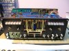
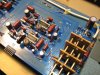
The same deoxit treatment mentioned above, was done to the pins on the pre amp board before it was pressed back into place. Then i pushed the connector piece that hooks the pre amp board to the Dolby board, back on. At this point, the whole thing has some rigidity and that makes it easier to slide the guts back into the chassis. With it sitting in the chassis almost in place, but still leaving you enough room to have access; reattach all the wires. The service manual shows the correct wiring connections, so i'm not going to list them here. With that done, it's ready to be pushed back in fully. Get the pins from the pre amp board lined up with the holes on the RCA board and push in until flush. Also position the Dolby FM adjustment pots and screw them back in. Now get the front piece to the chassis and slip it back into place. You may have to fiddle a little to get it down around all the pots and panel jacks, but it should go back into place pretty easily. Once situated, slip on all the washers, nuts and screws and tighten everything up. Put back in the spacers and screws that secure the selector buttons at the top as well. Reapply "thread locker" to all screws that used to have it before. Then turn the unit up on it's side and put back in all the screws on the bottom. Set it back down and put back in the lone PCB screw near the power supply. Now it is assembled and ready to test! (pic 3) If everything turned out ok and sounds fine, you are clear to go ahead and finish up the project. But that is not what happened to me.
 

Attachments

  • Reassembly 3.jpg
    Reassembly 3.jpg
    85.4 KB · Views: 188
  • Reassembly 2.jpg
    Reassembly 2.jpg
    93 KB · Views: 192
  • Reassembly 1.jpg
    Reassembly 1.jpg
    70.5 KB · Views: 164
Section 5: A new op-amp chip

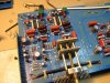
Ok, remember when i mentioned that i found a lot of threads by people having problems with the main IC inside this unit? Well, after all the work i did to bring my 3800 back to life, and maybe even make it better, this is exactly what happened to me. The first signals i sent though it came out highly distorted and low in volume. The volume and tone controls did little or nothing to the sound. After some discussions with Echowars and Catrafter, i thought maybe the biasing transistors had gone bad. Since the unit will run without them, i removed Q211 and Q212 and tried again. No difference. I checked the power supply voltages and found all to be where they should be. But some of the other pins on the IC were showing numbers WAY off the expected voltages. Eventually we came to the conclusion that the "X10" amplifier chip, a uA749PC, had gone bad. All through this project i had been quietly entertaining the ideal of how to upgrade this part, or deal with it's failing. But now i would have to make it happen. After consulting with dr*audio and EW about how to do it, i settled on trying an OPA 2134 as my replacement. I choose this op-amp due to the high praise it has received in the DIY phono pre thread, over in the Turntables forum. And according to EW, it and the 2132 op-amps, are well behaved and stable ICs. It also operated in the voltage range of the old 749PC, 18 volts.
 
Section 6: Fitting the new to the old . . .

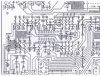
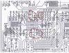
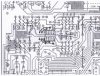
It doesn't take a rocket scientist to notice that the old IC has fourteen pins, and the new one has only eight. This is because the 749PC had to use an external compensation network to make it work properly. (A feature now built into modern op-amps.) This means all the parts involved in this external network, would no longer be needed if i used the new part. This would be very important for making the sub work, as those empty positions are needed for making new connections. The first step in determining what must be connected to what, is to find the datasheet for each part. I found the 749PC’s sheet at http://www.datasheetarchive.com/. The 2134's sheet was available at Digikey. Once you have this info, you need to see what each pin does in each IC. Which is + voltage in, - voltage in, +/- A input, +/- B input, A output and B output. In the case of the 749PC, the LAG ins and outs are what can be ignored. Taking that into consideration, some of the pins between the two ICs actually match, but others do not. As luck would have it though, those unmatched pin outs fall exactly on the spaces used by the compensation network. So all one must do is make jumpers to mate up the PCB connections to the correct pin outs. Below is a copy of the PCB layout from the service manual. (pic 1) Then in the next picture (pic2), circled in red are all the parts that must be removed. You will also need to pull the old fourteen pin IC socket. Picture three shows my crapply drawn diagram of the positions of the jumpers and the new eight pin IC socket.
 

Attachments

  • PCB layout 1.jpg
    PCB layout 1.jpg
    147.2 KB · Views: 241
  • PCB layout 2.jpg
    PCB layout 2.jpg
    146.8 KB · Views: 236
  • PCB layout 3.jpg
    PCB layout 3.jpg
    145.3 KB · Views: 237
Back
Top Bottom