• The move to the new server is done. There are some software and database maintenance updates in process. This has us passing the hat around to help out. We appreciate any donations. Seriously, even a dollar helps. The payment page may be found here - https://www.audiokarma.org/support.html

Restoring & modding a Marantz 3800

The 3800's Service Manual is rather poor in comparison to the 3300. I'm experiencing heavy distortion & lower output volume on the left channel. Also when the 400Hz tone button is depressed I get serious motorboating. ( I think that's the correct term) The right is performing perfectly. In the 3300 manual in the Trouble Analysis section, it gives specific parts to check for the specific problem. It also differentiates between Left & Right w/ parentheses. Wonder why this was not done for the 3800? I did print out an 18" x 24" of the Preamp Schematic & am going to go through the Times Ten Amplifier and the 400Hz tone Oscillator for my first suspects. Any guidance is much appreciated.

EDIT: I stand corrected - NOTE 5 - Odd numbers for Left.

Look at the x10 chip, common issue with the 3800.
 
If you are referring to the "X10" amplifier chip, a uA749PC, I just replaced that with one I just got off Ebay from Korea. I compared the 2, no difference. :(
 
Did you check the biasing transistors (2n5210)?
I found one to have little to no gain when I checked it.
I replaced both.
 
Hi All, If you're still monitoring this thread, I need some help diagnosing some very disturbing symptoms with my 3800 that JUST came back from the shop!
  1. There is modest output even when the volume is at zero. (Running either Aux input, or Tape 1. Will try other inputs as well, but may not use current speakers to test).
  2. Don’t get consistent, sufficient volume from amp as volume knob is turned up. (Expected performance and volume as connected to Hafler pre. The Marantz is rated almost identically to my DH220 amp – and seems to hit similar volume)
  3. Significant “pop” when turning on 3800 pre.
  4. After minutes of play – amplifier speaker relay begins cycling on/off coupled with serious “pop”.
  5. Observed woofers moving in-and-out slowly (ie: being “sucked” into the basket, then pushed back out – but no change in sound) then went into the “cycling” with poping and triggering the speaker relay in the amp.
 
Chris, you will get far more attention (and help) if you start your own thread.
 
To begin, you need to pull the following components:

Part #s Q211 & 212, C233, 234, 237 & 238, and R253 & 254. You also need to remove C239 and 241. Replace those two bypass caps with some .22uf Panasonic ECQ films. (Digikey part # P4667-ND) Since the voltage being supplied to the chip was only around 16.8 volts in my unit, i didn't replace the voltage dropping resistors (R267 & 268). But if in your 3800 you are getting much more than 17 V supplied, you should probably increase the value of these resistors. (The existing value is 10 ohms, so going up to as little as 47 ohms might be all it'd take.) I have been told it is not advisable to let an op-amp run very close to it's max operating voltage, if possible. Next, pull the fourteen pin chip socket and replace it with the eight pin socket.

Now the jumpers. Again, i made mine from leftover leads trimmed from the new capacitors.

Pins to jump are as follows:
Pin 5 to pin 3 via the empty pad for R253. This jumper must have heat shrink on it since it is so close to the new socket base. I put heat shrink on most of the other jumpers as well, but only this one must have it i feel.
Pin 6 to pin 2 via the empty pad of C237
Pin 7 to pin 4 via the empty pad of C233
Pin 8 to pin 12 via the empty pad for C238
Pin 9 to pin 11 via the empty pad for R254.

The jumpers are flush with the board and are bent/angled a bit to not interfere with each other and the new chip socket. None cross over. Picture one shows the emptied PCB, picture two shows the jumpers installed and picture three shows the new IC socket installed. Once everything is in place and cleaned up, power up and test to see of the right voltage is on the correct pin locations. If you put everything together right, it should be. If all is well, power down, instal the new op-amp and power back up. Pictures four & five show the 2134 in place and how everything looks. Now you are ready to calibrate.

Hello

First and foremost thank you for this informative thread.

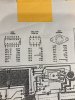
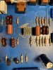
I am getting some different voltages than per this service manual. Are they all correct in the manual, after modification?

Will take voltages and post them later but curious if anyone else found an issue with the service manual.

I also swapped out the original voltage regulator for a replacement from eBay rc4194tk and for some reason pins 7 and 9 are reading voltages and not 0v.

Thanks
 

Attachments

  • image.jpg
    image.jpg
    141.5 KB · Views: 22
  • image.jpg
    image.jpg
    129 KB · Views: 23
Hello

First and foremost thank you for this informative thread.

I am getting some different voltages than per this service manual. Are they all correct in the manual, after modification?

Will take voltages and post them later but curious if anyone else found an issue with the service manual.

I also swapped out the original voltage regulator for a replacement from eBay rc4194tk and for some reason pins 7 and 9 are reading voltages and not 0v.

Thanks
Other than the jumper mod to make the more modern op amp work, wasn't there some resistors that had to be replaced with different values also? It's been a long time since I read the original mid thread. Why change the regulator, was it bad?
 
Back
Top Bottom