• Please note that Audiokarma will be offline briefly for updates early on Monday morning, September 28th.

Resurrection of a QRX-9001, or Restoration of a classic.

Livin4

Well-Known Member
A little background, I have a EE degree, but really haven't done any design work in over 20 years, and not much component level troubleshooting in over 10. Now it's mostly board or module swap.

I spent almost 10 years repairing consumer electronics, but never really understood how the different materials used in the manufacture of the components could affect the sound quality. My thinking was influenced by my previous supposition that a cap was a cap.

My 9001 was given to me back in 1990 by a friend who worked at the shop I was working in at the time. He said that he had an "old" stereo that didn't work and was kicking around in his basement, and that he really didn't want, and asked if I would be interested. With some reservations, I said yes, as the receiver I was using at the time (an Akai AA-1030 which I still have) couldn't drive the DBX Soundfield V's I had just bought.

When he brought it in, I started to drool, :drool: I couldn't believe he didn't want it. I managed to find a schematic at another shop, but the guy wanted me to bring it in to him for repair. I almost had to beg to get a copy. If I remember correctly, I paid him $20 for a copy of it, with the promise that I would let him copy manuals that we had, if he needed them. It had 1 bad channel, I found most of the transistors were toast, some bad caps, and resistors smoked as well.

After I repaired it, (for about $60 in parts I think) I couldn't believe the sound. At the time I only had 2 speakers, so it was always in 2 channel mode. I enjoyed it for several years before I got married. After I got married we really didn't have the room, as we lived in a mobile home, I was also afraid that my step sons would crank it, and blow it or the speakers when I was not there. And then my daughters got kittens... There was NO way I was going to let those little fur balls destroy the grills. So the 9001 and speakers sat (safe) in my parents basement. I bought a pair of Nova 18's, and we used the Akai, at 30 wpc, I didn't think they could blow the nova's.

When we finally bought a house, we still had cats, and now I was more afraid that the step-sons friends might steal it, so again it sat. In 2002 my wife died, and the step-sons were no longer around, and the cats were now outside pets! So I dug the 9001 out, hooked it up with the DBX's on the front, and the Nova's on the rear. It still sounded good, but I thought could hear some distortion, but did not have the money or time to look into it further. I used it intermittently for about 3 years, then I had a water leak in my basement, so all my audio equipment was moved and stored in another DRY room while the basement was remodeled.

Well here it is 7 years later, the Akai is still in regular use in my "library", and sounds ok, it needs some tuner work, and could really benefit from a re-cap. Ok, it just the spare bedroom that I have all my books and computer gear in, but a man can dream right?. And I picked up a JVC RX-888VB with remote from the local GW for $20, (just needed the volume control cleaned) to use for the big screen. Its running a set of Cerwin Vega HED's on the front, and the Nova 18's on the rear.


Here are some pics.
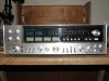
9001_front.jpg

And for those affectionados of the solid state form.
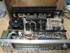
9001_top.jpg

So begins the odyssey....
 
Last edited:
Register to hide this ad
Nice story
Those Sansui's can out live us...I think you should grasp the challenge and get her done, somehow some way.
 
Well, finally ordered the caps and resistors suggested in other posts, and in emails with Trnsfmr, they should be here this Thursday. I will be starting with a general cleaning, just a bit of dust in there. :yuck:

SPOILER ALERT:
There will be pictures of naked electronics here. Those faint of heart should proceed at their own risk. :D
 
Good luck with your recap! I've got one sitting here that's collecting dust too..I'll get to it someday. They're complicated beasts. Maybe you can post that cap/resistor list.. I haven't found a complete one here on AK yet.
 
Good luck with your recap! I've got one sitting here that's collecting dust too..I'll get to it someday. They're complicated beasts. Maybe you can post that cap/resistor list.. I haven't found a complete one here on AK yet.

I would be happy to, but from what I have heard, the schematics and parts lists rarely match the units. So I am going to verify each part as I replace them.
 
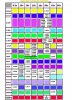
Here is my initial list.......
camman

Very nice, I like the format, easy to see quantity, value, and board. :thmbsp:

Right now mine is a little disorganized, I did it in Excel, 1 tab for each board. Each sheet lists info on the caps, resistors, and semiconductors parts on each board. I need to get it into a more logical format like yours. :)
 
Pre-power board done.

Well I finally had time to work on my Sansui, I started with the Pre-Power
supply board and replaced all the caps, and although the PCB layout in the
manual matches the board, I found a few discrepancies between the schematic and the actual board.

The first is that C01 and C04 are swapped on the board vs the schematic.
The schematic shows that C01 is a 220uf 25V, but on the board, it is a 100uf
25v, and the schematic shows C04 as a 100f 50V, but on the board, it is a
220uf 50v.

The second is that the schematic shows a C08, but the board does not have that, on the board it is labeled C09.

The third is that the schematic shows C05 across R04, but on the board the
negative lead of the cap actually connects between the wiper of VR01 and
R06.

I also installed a voltage regulator mod suggested by Trnsfmr. Then I powered it up. It still works! I then adjusted the pot on the pre-power board to set the 38.9v, all the other voltages measured good as well. The pots and switches need cleaning, and there seems to be some issues with the quad board, but I am sure some deoxit and fixing the pass through's will resolve that. The DC offsets are high, ranging from 35mv to 70mv, and I haven't checked the idle current yet. But all 4 channels work, and it came out of protection.

I am thinking that next I will do the driver boards and clean off the old
heat sink grease and apply new on the outputs. But the way my schedule is
looking, and since I am carefully comparing the schematic to the boards, it
may take awhile :(
 
Hi Livin4,
Just as you found on the little power board, most cap lists for old Sansuis are only a guide. We've tried several times to document everything and I don't think we've ever gotten it right.

And, Recappers Rule #1

Replace all parts with same value as existing on pc board. Schematic not important.


There are so many revisions, updates and whatever, realize that the schematic is only a guide. There are major fallacies on the 9001 schematic that I have and use regularly.
 
Livin4,
Can you post info for regulator mod?:thmbsp:
camman

Hey Camman, sorry about the delay, hectic work schedule. Here is the info on the modification, this is actually from Trnsfmr and he was kind enough to share it. You should also visit his web page, it has loads of info on the 9001.

http://www.qrxrestore.com/

Here is the info from him:

"I have added a 25v regulator to the 2639 PS board. I use a 7824 IC regulator to do it. I cut the trace where it goes to the output pin on the board and solder the input and output pins of the IC across the cut. To get 25v I hook the center, reference lead to ground through a 4148 diode, which give about a volt of drop across it, to push the voltage up to 25v. The ground point I use is the four unused holes toward the bottom of the board on that side. You have to use a small heat sink on the IC, and the dropping resistor that is normally there must be changed to 100 ohms. The stock one is a 180 ohm 2 watt. The IC's are not super accurate, but usually will get you within 1/2 v of 25."

I ordered the parts from Mouser and followed Trnsfmr's instructions, and it works great. Just remember to hook the cathode of the diode (end with line) to ground, and the anode to the middle pin of the 7824.
 
An update

Well it's been awhile, I have been working on the amp, and did run into some issues, but it is moving along.

First, the cap list I had I made from the schematic, and it is WRONG! Ok, only partially, but don't trust the schematic!! Like Trnsfmr says "Replace all parts with same value as existing on pc board". So the list I have is being modified as I go.

After the pre-power board I added a 12uf poly cap across the amp rails, and did the power supply board (2638) Here is where I found the next discrepancy, the schematic shows C603-C606 as 220uf 63v, but they were 100uf 63v on my unit.

Then I moved on to the driver boards (2624). These were pretty straight forward, except I didn't have the correct schematic for them. All of the schematics I have show using a transistor for temp compensation, where mine had the diode. Thanks again to Trnsfmr for pointing me to the 9090DB for the correct schematic for the boards. You will notice I am adding a .1uf poly cap in parallel with all of the lytics in the audio path, I opted to put them on the back sides of the boards.

And now, the part you've all been waiting for PICS! :D

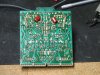
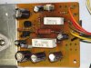
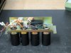
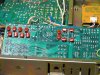
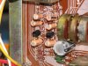
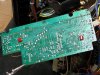
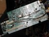
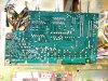
The first is of the poly cap placement for the PS rail. the next 2 are front and back of the pre-power board showing the 25v regulator mod, and the last 2 are front and back of the driver boards after replacing the caps, and fuseable resistors.
 

Attachments

  • Img_2595-1.jpg
    Img_2595-1.jpg
    110.4 KB · Views: 146
  • Img_2582-1.jpg
    Img_2582-1.jpg
    120.2 KB · Views: 148
  • Img_2606-1.jpg
    Img_2606-1.jpg
    75 KB · Views: 156
  • Img_2603-1.jpg
    Img_2603-1.jpg
    79.5 KB · Views: 155
  • Img_2569-1.jpg
    Img_2569-1.jpg
    60.7 KB · Views: 166
Last edited:
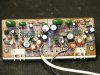
I completed the tone control and volume boards. Everything went smoothly, and it seems that the cap that Trsnfmr has found installed backwards in several units, was installed correctly in mine.

As you can see from the pics, I again opted to install the poly caps on the back of the boards, I have also cleaned off all the rosen from the solder using alcohol (IPA) and a stiff brush.

And I also used Deoxit on all controls and switch's.

First some before and after pics of one of the tone control boards.
 

Attachments

  • 2636_before.jpg
    2636_before.jpg
    81.4 KB · Views: 113
  • 2637_Front.jpg
    2637_Front.jpg
    66.4 KB · Views: 97
  • 2637_back.jpg
    2637_back.jpg
    60.9 KB · Views: 103
Last edited:
And some before and after of the volume control board showing C30.

Next is the surround boards, those should be fun.

Edit: The last picture shows .1uf poly caps on the back of the volume board parallel with all the caps in the audio path, while this looks really good, and keeps the top uncluttered, the bottom panel pressed on them when it was installed, and they in turn, flexed the board. :sigh: So not a good idea, unless your caps are smaller.
 

Attachments

  • 2636_back.jpg
    2636_back.jpg
    81 KB · Views: 97
  • 2636_front.jpg
    2636_front.jpg
    81.7 KB · Views: 88
  • 2636_C30.jpg
    2636_C30.jpg
    78.6 KB · Views: 91
  • 2636_before.jpg
    2636_before.jpg
    99.6 KB · Views: 92
Last edited:
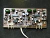
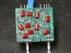
Slight change of plans, I did the 2689 protector board, and the 2634 4-ch function switch board.

First is the protector board.
 

Attachments

  • Before.jpg
    Before.jpg
    98.4 KB · Views: 84
  • After.jpg
    After.jpg
    122.5 KB · Views: 85
Last edited:
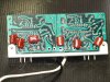
Next the 4-ch function switch board.

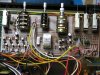
The 2634 4-ch function switch board is where all the nice little riveted pass-through's are, that was loads of fun. Especially the 2 on both sides of the relay, had to pull the relay to do those.
 

Attachments

  • Back.jpg
    Back.jpg
    110.2 KB · Views: 87
  • front.jpg
    front.jpg
    105.2 KB · Views: 90
Very cool! :D I recently bought a 9001 and its currently in the shop. Some day I will tackle the re-cap job, and your pics will be incredibly useful!
 
8-Months?

Where does the time go? Probably the same place as my memory. :scratch2:

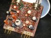
Well, I finished the 2633 Dolby change board, but it seems I only got a pic of the bottom. :sigh: I also did the 2688 Dolby board.

More pics to follow
 

Attachments

  • 2633_bot.jpg
    2633_bot.jpg
    93.3 KB · Views: 62
  • 2688_before_top.jpg
    2688_before_top.jpg
    78.5 KB · Views: 56
  • 2688_before_bot.jpg
    2688_before_bot.jpg
    75.7 KB · Views: 50
  • 2688_after_top.jpg
    2688_after_top.jpg
    68.5 KB · Views: 59
  • 2688_after_bot.jpg
    2688_after_bot.jpg
    81.3 KB · Views: 55
Back
Top Bottom